

Solution spun fiber process
a technology of spun fiber and fiber, applied in the direction of filament/thread forming, light and heating apparatus, fibre treatment, etc., can solve the problems of agglomeration of too many atomized droplets into larger entities, and achieve the effect of high throughput process
- Summary
- Abstract
- Description
- Claims
- Application Information
AI Technical Summary
Benefits of technology
Problems solved by technology
Method used
Image

Examples
example 1
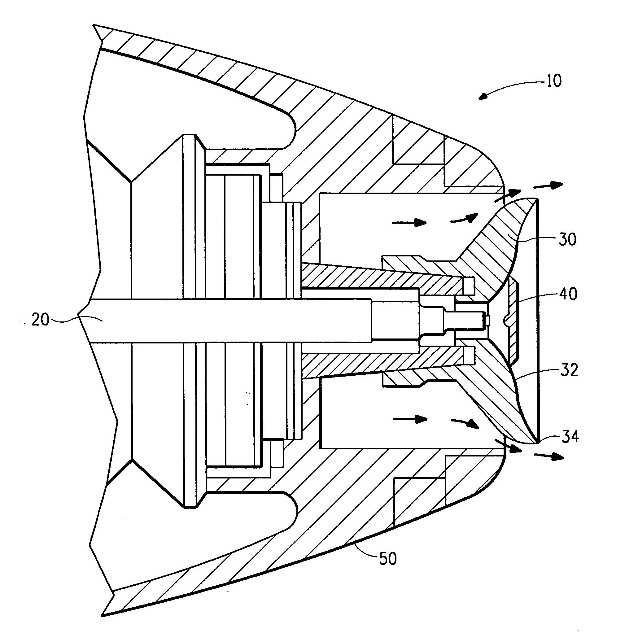
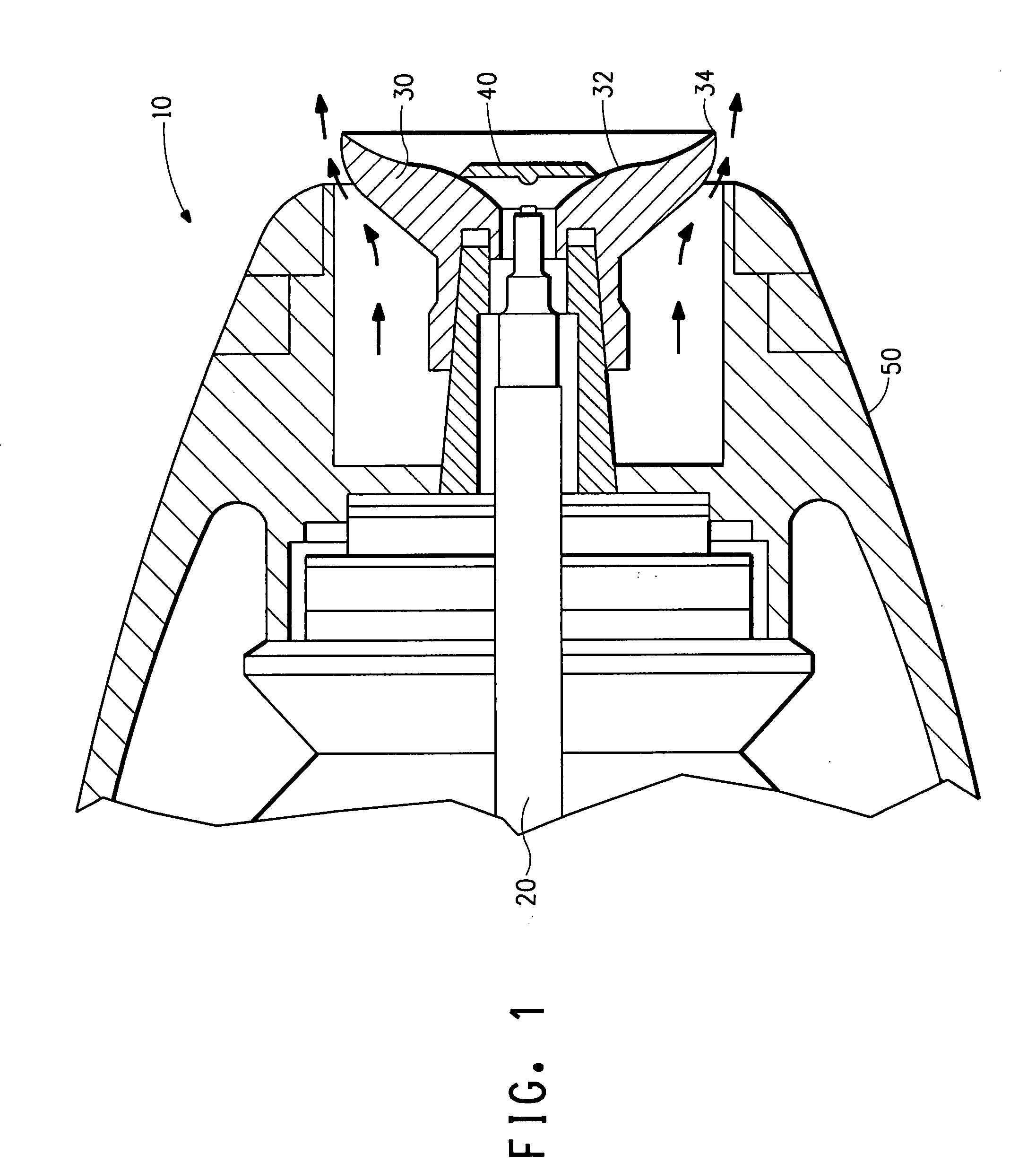
[0026] Continuous fibers were made using a standard Aerobell rotary atomizer and control enclosure for high voltage, turbine speed and shaping air control from ITW Automotive Finishing Group. The bell-shaped nozzle used was an ITW Ransburg part no. LRPM4001-02. A spinning solution of 10.0% poly(ethylene oxide) viscosity average molecular weight (Mv) of about 300,000, 0.1% sodium chloride, and 89.9% water by weight was mixed until homogeneous and poured into a Binks 83C-220 pressure tank for delivery to the rotary atomizer through the supply tube. The pressure on the pressure tank was set to a constant 15 psi. This produced a flow rate of about 2 cc / min. The shaping air was set at a constant 30 psi. The bearing air was set at a constant 95 psi. The turbine speed was set to a constant 40,000 rpm. No electrical field was used during this test. Fibers were collected on a Reemay nonwoven collection screen that was held in place 10 inches away from the bell-shaped nozzle by stainless stee...
example 2
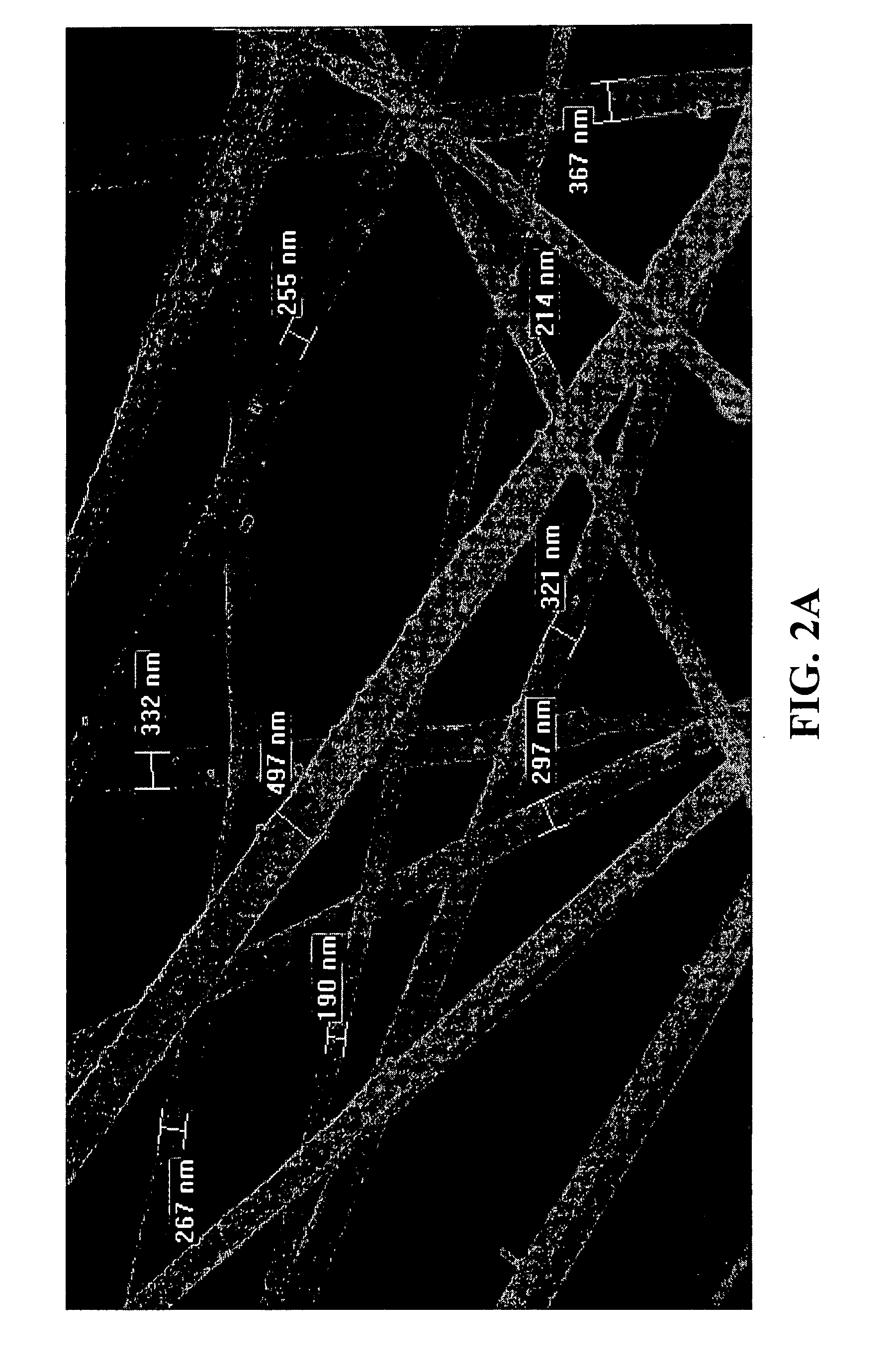
[0027] Example 2 was prepared similarly to Example 1, except an electrical field was applied. The electrical field was applied directly to the rotary atomizer by attaching a high voltage cable to the high voltage lug on the back of the rotary atomizer. The rotary atomizer was completely isolated from ground using a large Teflon stand so that the closest ground to the bell-shaped nozzle was the stainless steel sheet metal backing the Reemay collection belt. A +50 kV power supply was used in current control mode and the current was set to 0.02 mA. The high voltage ran at about 35 kV. The lay down of the fiber was much better than in Example 1 in that the coverage was very uniform over the collection area. The fiber size was measured from an image using SEM and determined to be in the range of 100 nm to 500 nm, with an average fiber diameter of about 350 nm. An SEM image of the fibers can be seen in FIG. 3a. FIG. 3b is a SEM image which shows the distribution of the fibers spun accordi...
example 3
[0028] Continuous fibers were made using a 65 mm “Eco Bell” serrated bell-shaped nozzle on a Behr rotary atomizer. A spin solution of 15% Evanol 80-18 poly(vinyl alcohol) and water by weight was mixed until homogeneous and poured into a pressure tank for delivery to the rotary atomizer through the supply tube. The viscosity of the spinning solution was 2,000 cP at 23° C. The pressure on the pressure tank was set to a constant pressure so that the flow rate was measured to be 17 cc / min. The shaping air was set at 100 SL / min. The turbine speed was set to a constant 50,000 rpm. An electrical field was applied directly to the rotary atomizer and the high voltage was set to 50 kV. Fibers were collected on a spunbond / meltblown / spunbond (SMS) composite nonwoven collection screen that was held in place 21 inches away from the bell-shaped nozzle by grounded stainless steel sheet metal. The fiber size was measured from an image using SEM and determined to be in the range of 100 nm to 600 nm w...
PUM
| Property | Measurement | Unit |
|---|---|---|
| viscosity | aaaaa | aaaaa |
| diameter | aaaaa | aaaaa |
| diameter | aaaaa | aaaaa |
Abstract
Description
Claims
Application Information