
Surface processing apparatus

Inactive Publication Date: 2008-02-14
OXFORD INSTR NANOTECH TOOLS
View PDF16 Cites 120 Cited by
  • Summary
  • Abstract
  • Description
  • Claims
  • Application Information

AI Technical Summary

Benefits of technology

[0018] The prior art teaches away from the use of a transmission plate because it is well known that excited and ionised plasma species are quickly quenched by contact with solid surfaces. Thus any technologies developed for use in altering generic gas flow are unsuitable for use in situations involving a plasma source and a connected processing chamber, due to the very different properties of the plasma species. Furthermore, whereas PECVD showerhead systems are designed to suppress plasma passing through the showerhead at all costs, the transmission plate is designed to allow active species to pass through the plate without significant quenching. By varying the fraction of plasma species that pass through different parts of the plate, a simple and effective means of optimising the uniformity of surface processing is provided.
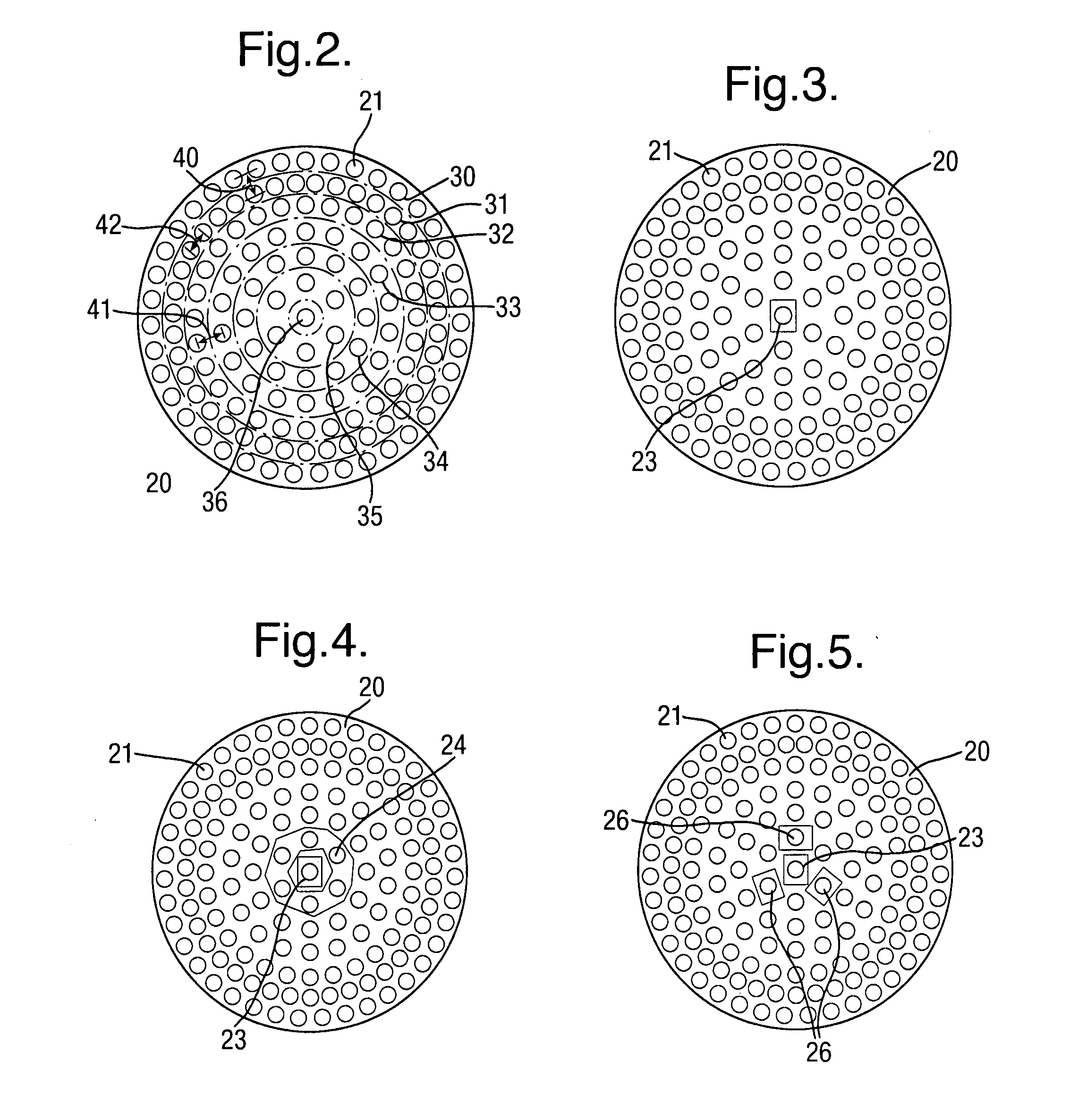
[0019] By controlling the features of a transmission plate mounted between a plasma source and a processing chamber, the present invention allows the careful control of the processing upon the surface of the substrate. Typically, the transmission plate will be designed so that the physical form and / or distribution of the one or more apertures is such that a uniform processing rate is provided across the surface of the substrate. Such a plate is simple to remove and replace if different processing patterns are required or if the transmission plate needs to be cleaned and replaced. This is in contrast to the use of predetermined nozzle geometry or RF coil configurations, wherein the method of providing uniformity is intrinsically bound with the complete HDPCVD apparatus. With the present invention, a transmission plate can also be changed for use with different plasma species.
[0024] To prevent the thermal degradation of the transmission plate, and to limit particles flaking from the transmission plate through thermal cycling, the thermal conductivity of the plate is typically greater than 100 W m-1 K-1 and the plate is thermally connected to an external chamber via a low thermal resistance path. The transmission plate can comprise either a metal or metal alloy plate. Alternatively a lower thermal conductivity material can be used with a lower thermal expansion coefficient, which can operate at higher temperatures, such as alumina ceramic. Where the transmission plate is to be used with chlorine-containing gas mixtures for etching, then alumina is preferred. It is also possible to use anodised aluminium or metal coated with a material more inert to the reactive plasma, such as plasma-sprayed alumina, to combine the beneficial effects of improved lateral heat conduction with inertness to the plasma.
[0035] Both gas mixtures can contain noble gases and both gas supplies may inject the same noble gas. This method further increases uniformity and the transmission plate limits the movement of undesired reactive gas species into the plasma source.

Problems solved by technology

Thus any technologies developed for use in altering generic gas flow are unsuitable for use in situations involving a plasma source and a connected processing chamber, due to the very different properties of the plasma species.

Method used


Image

  • Surface processing apparatus
  • Surface processing apparatus
  • Surface processing apparatus

Examples


Embodiment Construction

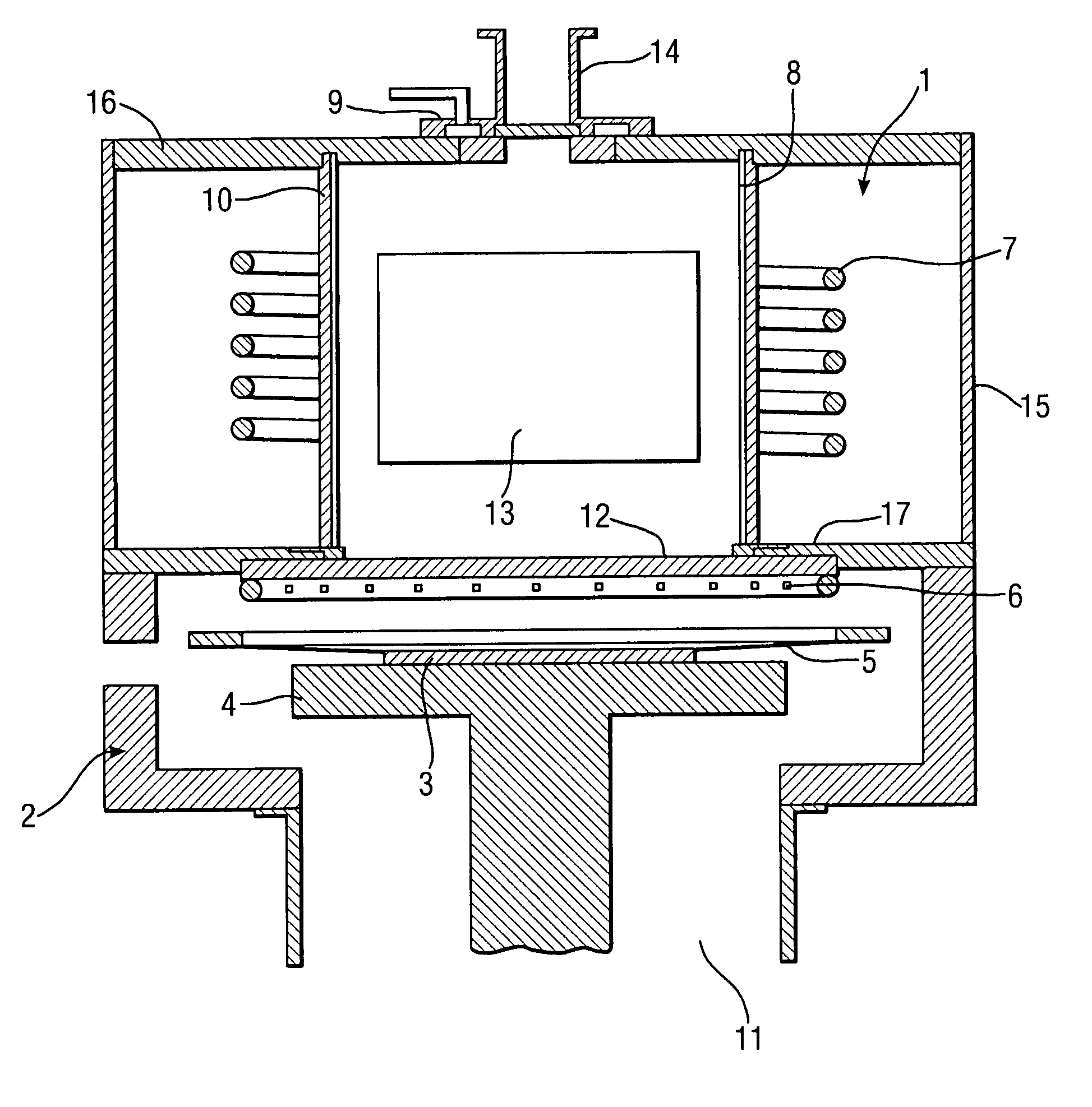
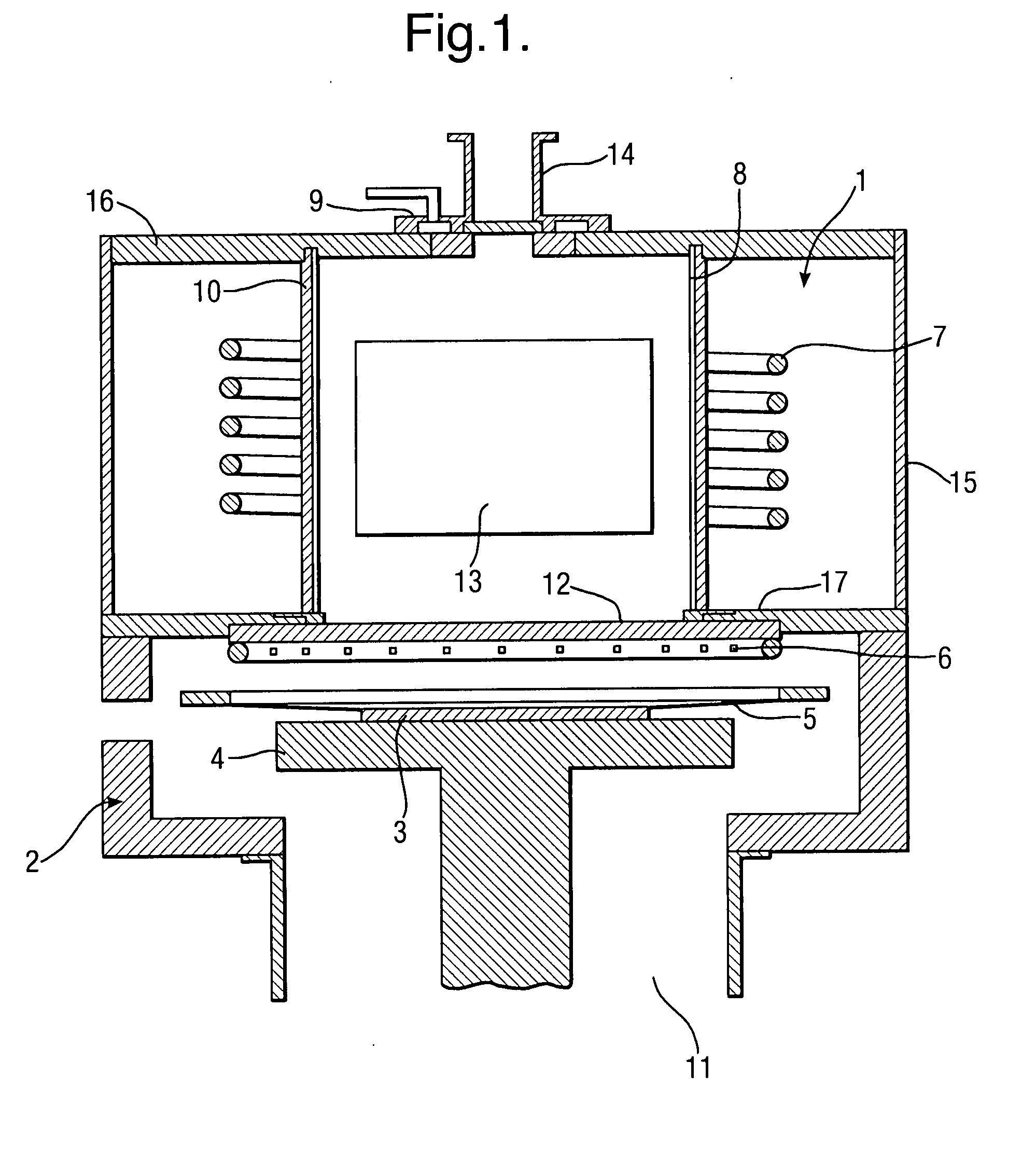
[0050]FIG. 1 is a schematic illustration of a high-density plasma chemical vapour deposition (HDPCVD) system. The system consists of two main components: a plasma source 1 and a processing chamber 2. The plasma source comprises a plasma chamber 8 constructed from a dielectric cylindrical tube with a vertical axis surrounded by an electrostatic shield 10. Typically, quartz or alumina is used as the dielectric. At the top of the cylindrical tube 8 is a set of gas inlets 9, which have an axially symmetric distribution and are used to inject a first gas or gas mixture into the plasma chamber used in the plasma generation. Beneficially, this first gas mixture includes a noble gas such as argon. This gas or gas mixture is ionised and excited within the plasma source 1, then transports to the processing chamber 2 by a combination of flow and diffusion.

[0051] Surrounding this plasma chamber 8 is a water-cooled radio frequency (RF) coil antenna 7 that forms an inductively coupled coil for u...


PUM

PropertyMeasurementUnit
Temperatureaaaaaaaaaa
Diameteraaaaaaaaaa
Diameteraaaaaaaaaa

Abstract

A surface processing apparatus is provided for use in the surface processing of a substrate. The surface processing apparatus comprises a plasma source and processing chamber in which a substrate is mounted in use. The processing chamber is operatively connected to the plasma source and the surface processing apparatus is characterised by a transmission plate for the transmission of plasma in use between the plasma source and processing chamber. The transmission plate comprises one or more apertures wherein the physical form of the one or more apertures and / or the distribution of the one or more apertures is adapted to provide a predetermined processing pattern upon the surface of the substrate. Typically the design of the apertures is adapted to provide a substantially uniform deposition rate across a wafer substrate.

Description

BACKGROUND OF INVENTION [0001] 1. Field of Invention [0002] The present invention relates to apparatus for the surface processing of a substrate, in particular apparatus that utilises high-density plasma to aid chemical vapour deposition or etching. [0003] 2. Description of the Related Art [0004] Chemical vapour deposition (CVD) and plasma etching are well-known processing methods used in the semiconductor and integrated circuit industry. In a standard CVD process a semiconductor wafer is placed within a specialised reaction chamber and the surface of the wafer is exposed to various chemical substances, wherein the chemical substances are injected into the reaction chamber in gaseous form or within a carrier gas. The chemical substances typically comprise one or more volatile precursors, which react with and / or decompose upon the wafer substrate to alter the surface of the semiconductor wafer and provide the necessary processing in dependence on the chemistry of the substances invol...

Claims


Application Information

Patent Timeline
IPC IPC(8): H01L21/306C23C16/00H05H1/24
CPCC23C16/452C23C16/45565H01J37/32623H01J37/32357H01J37/321
Inventor THOMAS, OWAIN PEREDURGRIFFITHS, ANDREW JOHN VASSILIOSCOOKE, MICHAEL JOSEPH
Owner OXFORD INSTR NANOTECH TOOLS
Learn More