
Hexagonal Ferrite, Antenna Using The Same And Communication Apparatus

a technology of hexagonal ferrite and antenna, applied in the field of magnetic materials, can solve the problems of increasing the increasing the cost of ferromagnetic core, etc., and achieves excellent loss factor, high and excellent density of sintered body.

Inactive Publication Date: 2008-02-14
HITACHI METALS LTD
View PDF1 Cites 16 Cited by
  • Summary
  • Abstract
  • Description
  • Claims
  • Application Information

AI Technical Summary

Benefits of technology

The invention is a hexagonal ferrite that has a high density of sintered body and low loss factor, making it suitable for applications in high frequency ranges such as digital terrestrial broadcasting. The hexagonal ferrite contains Y-type ferrite as the main phase, with a low level of loss and high magnetic permeability. The addition of Li and the use of specific combinations of M2, M2', and M2" can further improve the density of sintered body, magnetic permeability, and magnetic permeability at high frequencies. The hexagonal ferrite is also suitable for antennas and communication apparatuses due to its wide bandwidth and high gain.

Problems solved by technology

As a result, the bandwidth decreases and it becomes difficult to apply the chip antenna to applications that require wide bandwidths, such as digital terrestrial broadcasting.
However, when Z-type ferrite is used as the magnetic material, loss is large and the magnetic permeability starts decreasing at several hundreds of MHz, so that it is difficult to achieve satisfactory antenna characteristics in the frequency range of several hundreds of MHz or higher.
When Y-type ferrite is used as the magnetic material, the loss is small and the magnetic permeability does not decrease even in the range of several GHz or higher, but the following problems occur.
A high density of sintered body is also required because low density of sintered body likely cause chipping when the material is machined.
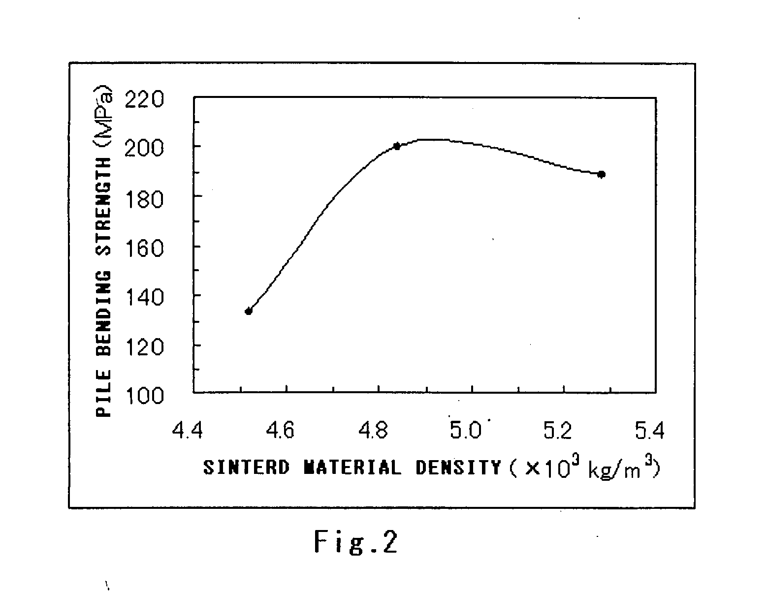
However, in the case of Y-type ferrite, it is difficult to achieve a high density of sintered body density and hence high strength, while preventing increase in loss.
For example, simply controlling the sintering temperature or the like to increase the density of sintered body causes abnormal grain growth, resulting in degraded magnetic characteristics.
For example, the magnetic oxide sintered body disclosed in JP-A-2002-260912 hardly solves the problem associated with the loss and also has a high dielectric constant, so that it is difficult to directly apply that material to antenna applications.
The fact that it is difficult to achieve high density of sintered body while preventing increase in loss makes it difficult to apply Y-type ferrite not only to a chip antenna but also to other electronic apparatuses used in high frequency ranges.

Method used


Image

  • Hexagonal Ferrite, Antenna Using The Same And Communication Apparatus
  • Hexagonal Ferrite, Antenna Using The Same And Communication Apparatus
  • Hexagonal Ferrite, Antenna Using The Same And Communication Apparatus

Examples


example 1

[0046] Fe2O3, BaCO3, SrCO3, CO3O4 and NiO were weighed such that each oxide magnetic material had a predetermined composition shown in Table 2, and then SiO2, Na2CO3, Li2CO3 and Mn3O4 were added in the amounts indicated in Table 2 with respect to 100 weight parts of the main components, followed by mixing the thus weighed components in the wet ball mill using water as a medium for 16 hours.

[0047] The mixed powder was dried and then calcined in the air at 1000° C. for 2 hours. The resultant calcined powder was ground in the wet ball mill using water as a medium for 18 hours. The binder (PVA) in the amount of 1% was added to the resultant ground powder for granulation. Upon granulation, the resultant granules were compressed into a ring shape. Thereafter, the shaped granules were sintered in an oxygen atmosphere at 1200° C. for 3 hours. The resultant ring-shaped sintered body having an outer diameter of 7.0 mm, an inner diameter of 3.5 mm and a height of 3.0 mm underwent a process of...

example 2

[0051] Sintered body were fabricated as in Example 1 except that the molar ratios of the main components Fe2o3, BaO (BaCO3 was used) and CoO (Co3O4 was used) were 60 mol %, 20 mol % and 20 mol %, respectively, and Li2CO3, CuO and ZnO were contained in the amounts indicated in Table 4 with respect to 100 weight parts of the main components. Table 4 shows the results of measurement of the density of sintered body, the volume resistivity, the magnetic permeability μ, the loss factor tan δ and the dielectric constant ∈ performed as in Example 1.

TABLE 4VolumeMagneticDielectricLi2CO3CuOZnODensity ×resistivity ×permeabilityLoss factorconstant(Weight(Weight(Weight103105μtanδεNo.Part)Part)Part)(kg / m3)(Ω· m)(1 GHz)(1 GHz)(1 GHz)37Example0.20.404.843.42.80.055.138Example0.20.604.803.12.90.055.039Example0.21.305.200.42.70.045.340Example0.21.505.300.21.50.014.741Example0.40.405.181.12.90.064.842Example0.40.605.320.82.70.054.743Example0.41.005.132.02.80.044.944Example0.41.505.072.32.40.024.945E...

example 3

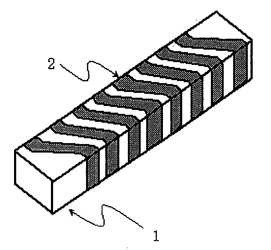
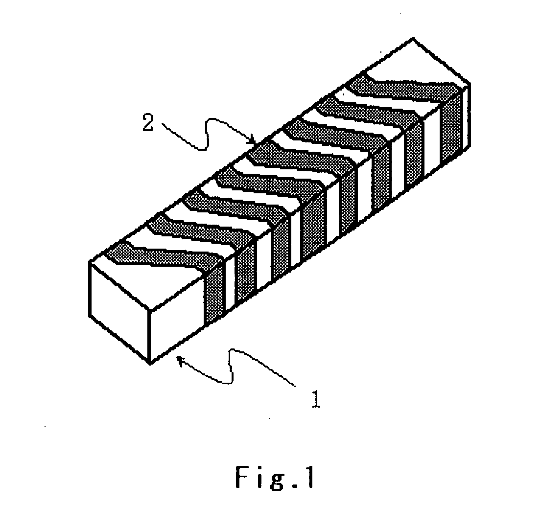
[0053] Some of the materials in Examples 1 and 2 were used to fabricate block-shaped sintered body each of which was machined into a shape having a dimension of 15 mm by 3 mm by 3 mm. Ag—Pt paste was printed and sintered onto the surface of each of the sintered body to fabricate a chip antenna with an electrode having a helical structure configured such that the electrode width and the electrode gap were 0.8 mm and 0.5 mm, respectively, and the number of winding was eight. FIG. 1 shows the exterior of the fabricated chip antenna. Each of the chip antennas was mounted on a substrate and one end of the helical electrode was connected to a feeding electrode. Then, an antenna gain evaluation apparatus using a network analyzer was used to evaluate antenna characteristics (resonant frequency, full width at half maximum of gain). Table 5 shows the evaluation results. As shown in Table 5, each of the chip antennas using the hexagonal ferrite of this example achieved a maximum gain of −10 dB...


PUM

PropertyMeasurementUnit
frequencyaaaaaaaaaa
dielectric constantaaaaaaaaaa

Abstract

There is provided Y-type hexagonal ferrite having a high density of sintered body and a low level of loss and an antenna. The hexagonal ferrite having Y-type ferrite as the main phase is characterized in that main components of the hexagonal ferrite are M1O (M1 stands for at least one of Ba and Sr), M2O (M2 stands for at least one of Co, Ni, Cu, Zn and Mn) and Fe2O3, and the loss factor and the density of sintered body are 0.15 or lower and 4.6×10³ kg / m3 or higher, respectively. The hexagonal ferrite is used to configure an antenna and a communication apparatus.

Description

TECHNICAL FIELD [0001] The present invention relates to magnetic material suitable for high frequency devices, and particularly to hexagonal ferrite suitable for use in a high frequency band ranging from several hundreds of MHz to several GHz, an antenna used in communication apparatuses, such as mobile phones, wireless LANs and digital broadcasting, and a communication apparatus. BACKGROUND ART [0002] In recent years, as miniaturized, high-speed, high-frequency electronic apparatuses have been introduced, circuit components used in such apparatuses need to have characteristics usable in a range from several hundreds of MHz to several GHz. For example, impedance elements for noise reduction need to maintain high impedance in the above high frequency band. As another example, communication apparatuses, such as mobile phones and wireless LANs, operate in a frequency band ranging from several hundreds of MHz to several GHz and need to be able to operate in a wide band and to have high ...

Claims


Application Information

Patent Timeline
Patent Type & Authority Applications(United States)
IPC IPC(8): C04B35/26H01F1/34H01Q1/00
CPCC04B35/2633C04B2235/3215C04B2235/3274C04B2235/767C04B2235/77H01Q11/08H01F1/36H01Q1/1242H01Q1/362H01Q7/08H01F1/348C04B35/26H01Q1/38H01F1/34
Inventor GONDA, MASAYUKIAOYAMA, HIROYUKI
Owner HITACHI METALS LTD
Learn More