Method to form a pattern of functional material on a substrate

Inactive Publication Date: 2008-04-10
EI DU PONT DE NEMOURS & CO
View PDF19 Cites 39 Cited by
  • Summary
  • Abstract
  • Description
  • Claims
  • Application Information

AI Technical Summary

Benefits of technology

[0010]The present invention provides a method to form a pattern of functional material on a substrate. The method includes providing an elastomeric stamp having a relief structure with a raised surface, the stamp having a modulus of elasticity of at least 10 MegaPascal. A liquid composition comprising the functional mat

Problems solved by technology

Photolithography, however, is a complex, multi-step process that is too costly for the printing of plastic electronics.
SAM printing is capable of creating high resolution patterns, but is generally limited to forming metal patterns of gold or silver with thiol chemistry.
Although it has been shown that 20 nm features can be ac

Method used


Image

  • Method to form a pattern of functional material on a substrate
  • Method to form a pattern of functional material on a substrate
  • Method to form a pattern of functional material on a substrate

Examples


example 1

[0064]The following example demonstrates printing of a light emitting polymer (LEP) onto a substrate with a printing stamp made of polyfluoropolyether (PFPE).

Printing Stamp Preparation

Master Preparation:

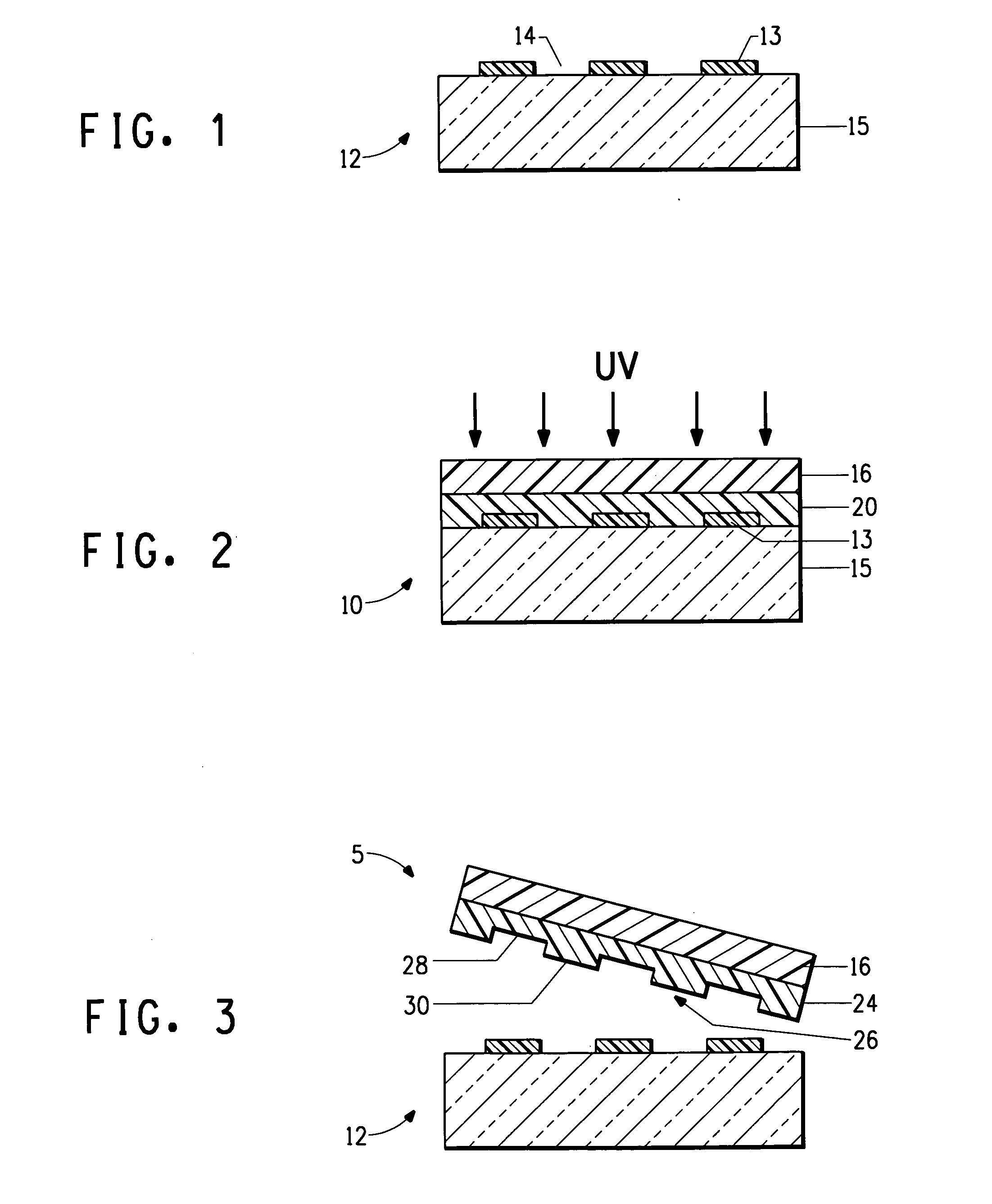
[0065]A 1.5 micrometer thick layer of a negative photoresist, SU-8 type 2 (from MicroChem, Newton, Mass.) was coated onto a silicon wafer at 3000 rpm for 60 sec. The wafer with the coated photoresist film was heated 65° C. for 1 minute and then baked at 95° C. for 1 minute to fully dry the film. The baked film was then exposed for 12 sec in I-liner (OAI Mask Aligner, Model 200) at 365 nm through a mask having a pattern of lines and spaces and squares with dimensions varying from 1 to 5 micron, and post-baked at 65° C. for 1 min. After a final bake at 95° C. for 1 minute the exposed photoresist was developed in SU-8 developer for 1 minute and washed with isopropyl alcohol. The developed film was dried with nitrogen and formed a pattern on the wafer, which was used as a master for the ...

example 2

[0081]The following example demonstrates printing of another light emitting polymer (LEP) onto a substrate with a printing stamp made of PFPE.

[0082]The master and the PFPE stamp were prepared as described in Example 1.

Printing of LEP on Substrate:

[0083]The LEP solution was OC1-C10 which is a poly(p-phenylenevinylene) derivative from Hoechst, and has the following structure.

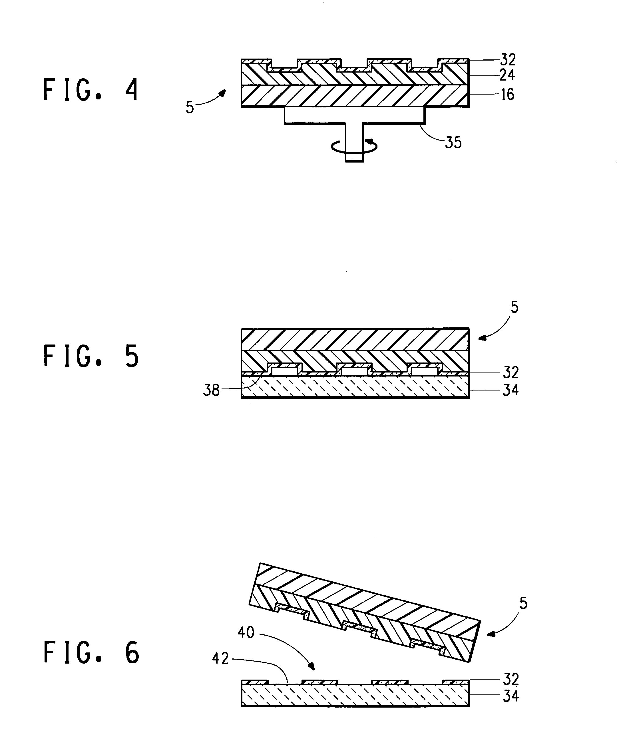
[0084]A 0.5% by weight solution of the OC1-C10 in THF / toluene (50 / 50 v / v) was prepared and maintained in a nitrogen dry box. The solution was spun coated onto the relief surface of the PFPE stamp at 4500 rpm in a dry nitrogen atmosphere to coat and dry the OC1-C10 as a layer on the stamp.

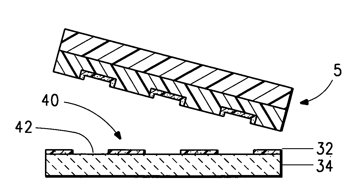
[0085]The substrate used was the same as the substrate described in Example 1. The OC1-C10 on the uppermost surface of the raised portions of the PFPE was printed by contact transfer onto the ITO surface of the substrate. The transfer was accomplished by placing the ITO substrate on hot plate maintained at 65° C. under a dry nitro...

example 3

[0086]The following example demonstrates printing of a dielectric material onto a substrate with a printing stamp made of PFPE.

[0087]The dielectric materials printed were Elvacite® 2042, a poly(ethyl methacrylate), and Elvacite® 2045, a poly(butyl methacrylate), both from Lucite International. The substrate was a silicon wafer having a layer of SiO2 that had a thickness of about 3000 Angstrom.

[0088]For both of the printed samples of Example 3, the master and the PFPE stamp were prepared as described in Example 1, except that a different PFPE compound having a molecular weight of about 1000, and a different photoinitiator were used.

[0089]The perfluoropolyether compound E10-DA was used as received and supplied by Sartomer as product type CN4000. The E10-DA has a structure according to the following Formula, wherein R and R′ are each an acrylate, E is a linear non-fluorinated hydrocarbon ether of (CH2CH2O)1-2CH2, and E′ is a linear hydrocarbon ether of (CF2CH2O(CH2CH2O)1-2, and having ...


PUM

PropertyMeasurementUnit
Temperatureaaaaaaaaaa
Diameteraaaaaaaaaa
Massaaaaaaaaaa

Abstract

The invention provides a method to form a pattern of a functional material on a substrate. The method uses an elastomeric stamp having a relief structure with a raised surface and having a modulus of elasticity of at least 10 MegaPascal. A liquid composition of the functional material and a liquid is applied to the relief structure and the liquid is removed to form a film on the raised surface. The elastomeric stamp transfers the functional material from the raised surface to the substrate to form a pattern of the functional material on the substrate. The method is suitable for the fabrication of microcircuitry for electronic devices and components.

Description

BACKGROUND OF THE INVENTION[0001]1. Field of the Invention[0002]This invention pertains to a method for forming a pattern of functional material on a substrate, and in particular, the method uses an elastomeric stamp having a raised surface to form the pattern on the substrate for use in microfabrication of components and devices.[0003]2. Description of Related Art[0004]Nearly all electronic and optical devices require patterning. Microelectronic devices have been prepared by photolithographic processes to form the necessary patterns. According to this technique a thin film of conducting, insulating or semiconducting material is deposited on a substrate and a negative or positive photoresist is coated onto the exposed surface of the material. The resist is then irradiated in a predetermined pattern, and irradiated or non-irradiated portions of the resist are washed from the surface to produce a predetermined pattern of resist on the surface. To form a pattern of a conducting metal m...

Claims


Application Information

Patent Timeline
IPC IPC(8): B44C1/17C21B9/00
CPCB82Y10/00G03F7/0002B82Y40/00G03F7/00B82B3/00B82B1/00
Inventor BLANCHET, GRACIELA BEATRIZLEE, HEE HYUNJAYCOX, GARY DELMAR
Owner EI DU PONT DE NEMOURS & CO
Why Eureka
Try Eureka