Production Method of Thermoelectric Semiconductor Alloy, Thermoelectric Conversion Module and Thermoelectric Power Generating Device

a production method and technology of thermoelectric semiconductor alloy, applied in the manufacture/treatment, transportation and packaging of thermoelectric devices, thermoelectric devices, etc., can solve the problems of increasing cost and a great deal of effort, and achieve the effect of low cost and high performan

Inactive Publication Date: 2008-04-24
SHOWA DENKO KK
View PDF2 Cites 61 Cited by
  • Summary
  • Abstract
  • Description
  • Claims
  • Application Information

AI Technical Summary

Benefits of technology

[0038] According to the present invention, a thermoelectric conversion module and a thermoelectric power generating device each exhibiting high performance over a wide temperature range from a low temperature near room

Problems solved by technology

For enhancing the performance of each material, a great deal of effort is being made.
In the case of using a Heuslar alloy as a thermoelectric semiconductor, the design is difficult due to numerous combinations of elements, a

Method used


Image

  • Production Method of Thermoelectric Semiconductor Alloy, Thermoelectric Conversion Module and Thermoelectric Power Generating Device
  • Production Method of Thermoelectric Semiconductor Alloy, Thermoelectric Conversion Module and Thermoelectric Power Generating Device
  • Production Method of Thermoelectric Semiconductor Alloy, Thermoelectric Conversion Module and Thermoelectric Power Generating Device

Examples


example 1

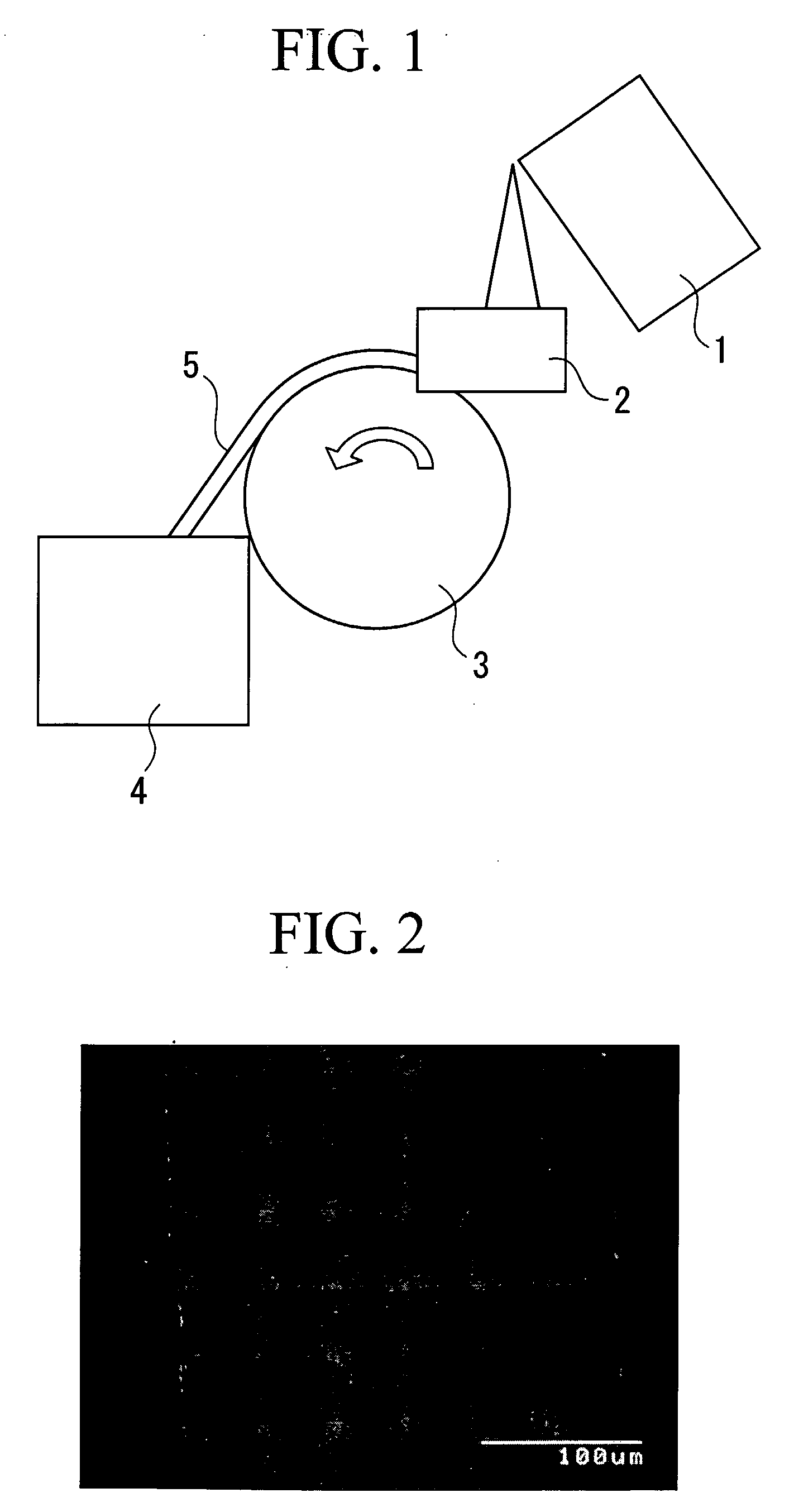
[0065] Sponge Ti (purity: 99% or more), sponge Zr (purity: 99% or more), electrolytic Ni (purity: 99% or more) and Sn metal (purity: 99.9% or more) were weighed to give a half Heuslar-type (TixZr1-x)NiSn composition after casting, and high-frequency melted at a temperature up to 1,700° C. under 0.1 MPa in an Ar atmosphere. Thereafter, by using a strip casting apparatus shown in FIG. 1, the molten metal was poured from the crucible 1 through the tundish 2 on the water-cooled copper roll 3 rotating at a spherical velocity of 0.9 m / sec to produce an alloy flake 5, and the alloy flake was collected in the container 4. The average thickness of the alloy flake 5 was 0.25 mm. In this casting, the cooling rate was estimated to be about 7×10²° C. / sec.

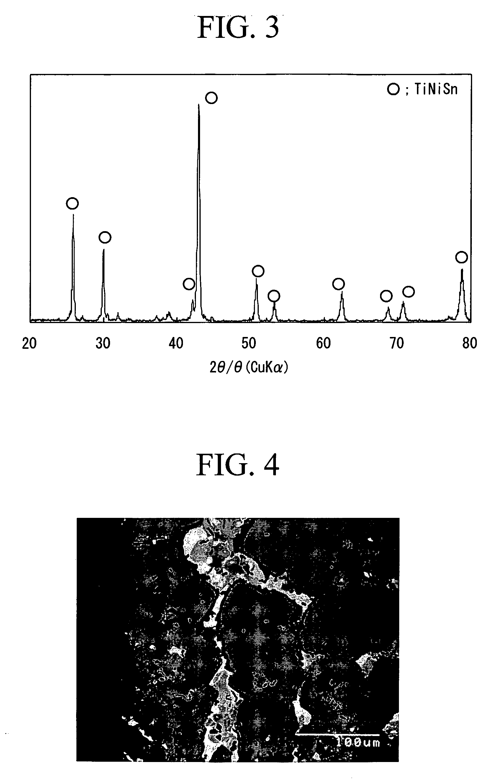
[0066]FIG. 2 is a back scattered electron image showing the cross section of the alloy obtained as above. As seen from this, the alloy flake has a uniform structure in the entire region. Also, it is known from the X-ray diffraction pattern of F...

example 2

[0073] Electrolytic iron (purity: 99% or more), ferrovanadium (Fe-V, JIS FV1, V purity: 87%) and Al metal were weighed to give a Heuslar-type Fe2(VxTi1-x)(AlySi1-y) (020 shown in FIG. 1, the molten metal was poured from the crucible 1 through the tundish 2 on the water-cooled copper roll 3 rotating at a spherical velocity of 0.9 m / sec to produce an alloy flake 5, and the alloy flake was collected in the container 4. The average thickness of the alloy flake 5 was 0.28 mm. In this casting, the cooling rate was estimated to be about 7×10²° C. / sec. FIG. 5 is a back scattered electron image showing the cross section of the alloy obtained, and FIG. 6 is a powder X-ray diffraction pattern of the alloy. As seen from these, a Heuslar alloy comprising a single phase can be obtained by the quench-solidification method. The ratio of strongest peak of the Fe2VAl was 100%.

[0074] This alloy was ground to 200 μm or less by a stamp mill and then pulverized at 0.5 MPa in a nitrogen steam by a jet mi...


PUM

PropertyMeasurementUnit
Fractionaaaaaaaaaa
Particle diameteraaaaaaaaaa
Cooling rateaaaaaaaaaa

Abstract

The present invention provides a method for producing a half Heuslar alloy including quench-solidifying a molten alloy at a cooling rate of 1×10² to 1×10³° C./sec to produce a Heuslar alloy represented by the formula: ABC (wherein A and B each is at least one member selected from transition metals such as Fe, Co, Ni, Ti, V, Cr, Zr, Hf, Nb, Mo, Ta and W, and C is at least one member selected from Group 13 or 14 element such as Al, Ga, In, Si, Ge and Sn), and a high-performance thermoelectric power generating device using the thermoelectric semiconductor alloy.

Description

TECHNICAL FIELD [0001] The present invention relates to a production method of a thermoelectric semiconductor alloy, and a high-performance thermoelectric power generating device using a thermoelectric semiconductor alloy produced by the production method. [0002] This application claims the benefit pursuant to 35 U.S.C. § 119 (e) of U.S. Provisional Application No. 60 / 640,242 filed on Jan. 3, 2005, and priority is claimed on Japanese Patent Application No. 2004-374218, filed Dec. 24, 2004, the contents of which are incorporated herein by reference. BACKGROUND ART [0003] To cope with the regulation for emission of carbonic acid gas and energy conservation, thermoelectric power generation utilizing thermoelectric conversion of converting waste heat directly into electricity is attracting attention. This thermoelectric conversion is effected by such a mechanism that when temperature difference is generated by assigning one end of n-type and p-type semiconductors to a high temperature a...

Claims


Application Information

Patent Timeline
IPC IPC(8): H01L35/20C22C1/00C22C30/00C22C30/04B22F1/068
CPCB22F1/0055B22F9/10B22F2998/00C22C1/0491C22C30/00H01L35/34C22C30/04H01L35/20B22F1/068C22C1/047H10N10/854H10N10/01
Inventor NAKAJIMA, KENICHIRO
Owner SHOWA DENKO KK
Why Eureka
Try Eureka