Movable body system, pattern formation apparatus, exposure apparatus and exposure method, and device manufacturing method

a technology of movable bodies and pattern formation equipment, applied in the direction of photomechanical equipment, instruments, printing, etc., can solve the problems of high probability of a position measurement accuracy decline, encoders with a drawback of lack of measurement value linearity, and inferior long-term stability when compared with laser interferometers, so as to reduce the size of the movable body

Inactive Publication Date: 2008-04-24
NIKON CORP
View PDF56 Cites 157 Cited by
  • Summary
  • Abstract
  • Description
  • Claims
  • Application Information

AI Technical Summary

Benefits of technology

[0019] According to this method, because switching is performed from a measurement of the positional information of the movable body using one of the measurement units of the first and second measurement units to a measurement of the positional information of the movable body using the other measurement unit, position control of the movable body can be performed without any problems in particular even if the size of the movable body is reduced.

Problems solved by technology

However, requirements for a stage position control with higher precision are increasing due to finer patterns that accompany higher integration of semiconductor devices, and now, short-term variation of measurement values due to temperature fluctuation of the atmosphere on the beam path of the laser interferometer and / or the influence of temperature gradient has come to occupy a large percentage in the overlay budget.
Meanwhile, as a measurement unit besides the laser interferometer used for position measurement of the stage, an encoder can be used, however, because the encoder uses a scale, which lacks in mechanical long-term stability (drift of grating pitch, fixed position drift, thermal expansion and the like), it makes the encoder have a drawback of lacking measurement value linearity and being inferior in long-term stability when compared with the laser interferometer.
However, in the case a mirror of the interferometer or a scale (such as a grating) of the encoder is arranged on the outside, such as, for example, on the side surface of a stage, a position (positional relation with a predetermined point on the stage) on the stage changes along with the minute deformation of the stage which occurs when the stage is accelerated, which makes the probability high of a decrease in the position measurement precision of the stage.
Further, for example, from the viewpoint of improving throughput, even if a new technology was proposed of beginning exposure during the acceleration of the wafer stage in a scanning stepper, there is a risk that the change of the position of the mirror or the scale on the stage that accompanies the acceleration of the stage described above will become an obstacle factor when practicing the new technology.

Method used


Image

  • Movable body system, pattern formation apparatus, exposure apparatus and exposure method, and device manufacturing method
  • Movable body system, pattern formation apparatus, exposure apparatus and exposure method, and device manufacturing method
  • Movable body system, pattern formation apparatus, exposure apparatus and exposure method, and device manufacturing method

Examples


first embodiment

A First Embodiment

[0034] An embodiment of the present invention will be described below, with reference to FIGS. 1 to 3C.

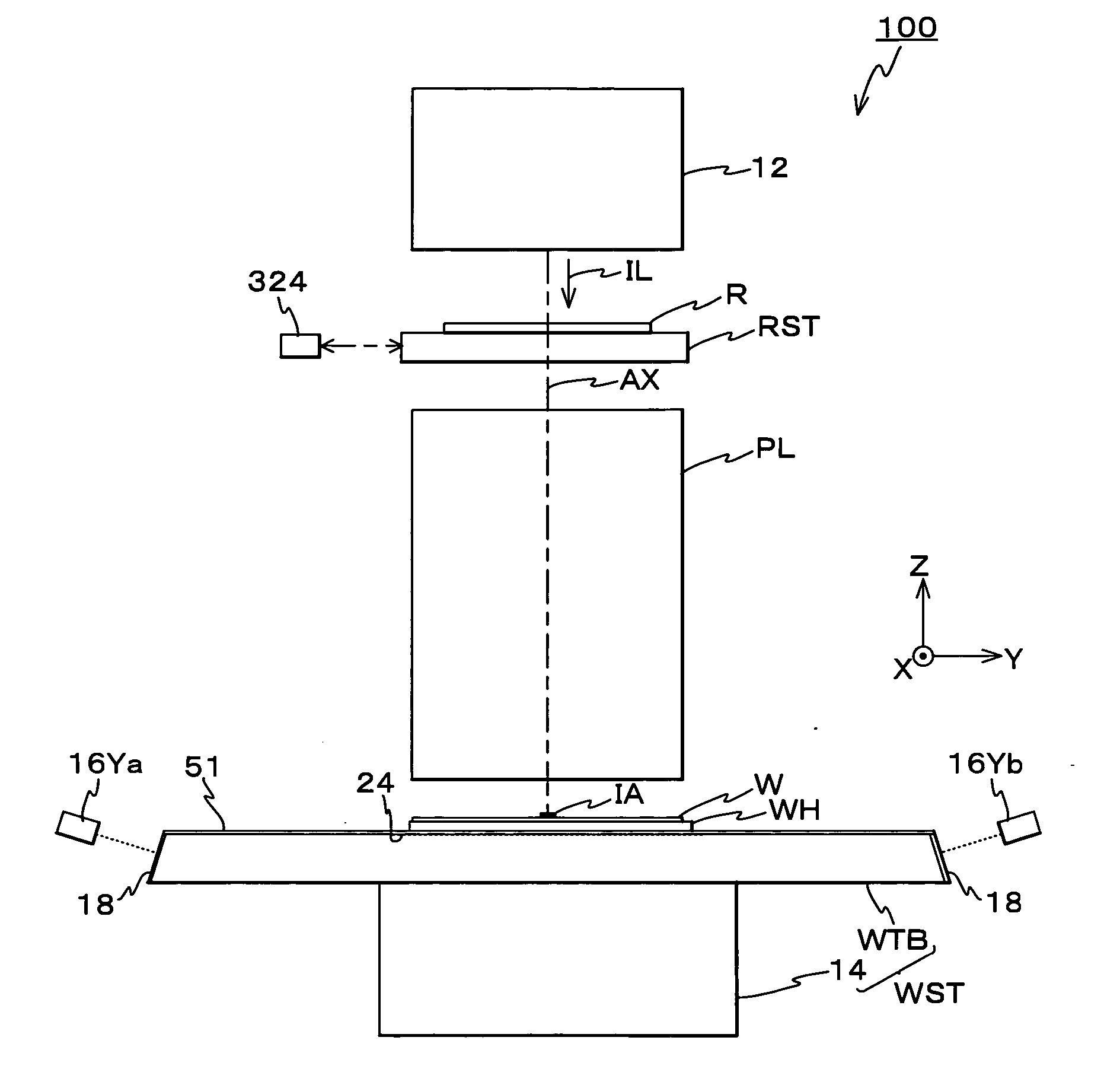
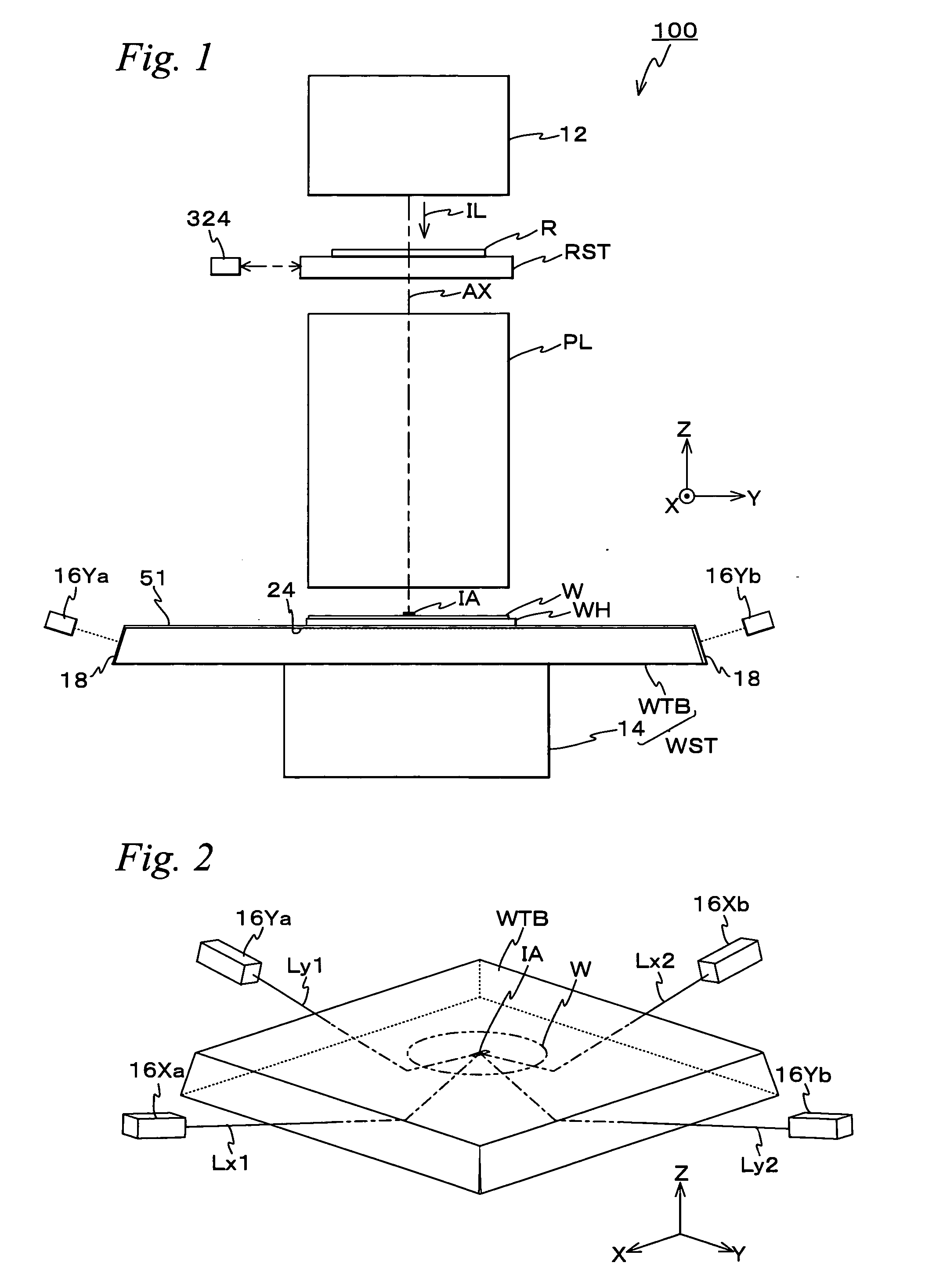
[0035]FIG. 1 shows a schematic configuration of an exposure apparatus 100 related to the first embodiment of the present invention. Exposure apparatus 100 is a reduction projection exposure apparatus by a step-and-scan method. Exposure apparatus 100 is equipped with an illumination system 12 including a light source and an illumination optical system and illuminates a reticle R by an illumination light IL, a reticle stage RST that holds reticle R, a projection optical system PL, a wafer stage WST that holds wafer W, a controller (not shown) which has overall control over the system and the like. In the description below, a direction parallel to an optical axis AX of projection optical system PL will be described as the Z-axis direction, a direction within a plane orthogonal to the Z-axis direction in which a reticle and a wafer are relatively scanned will be desc...

second embodiment

A Second Embodiment

[0068] Next, a second embodiment of the present invention will be described, referring to FIGS. 5A to 5C. As shown in FIGS. 5A to 5C, in the second embodiment, the point where a wafer table WTB slightly larger than wafer holder WH is used as wafer table WTB is different from the first embodiment previously described (FIG. 2), however, the other configuration and the like is similar to the first embodiment. Accordingly, the description below will be made focusing on this difference, and in order to avoid redundancy, the same reference numerals will be used for the same or similar sections and a detailed description thereabout will be omitted. Incidentally, the size of wafer table WTB in the second embodiment is almost the same as wafer table WTB shown in FIGS. 4A to 4C.

[0069] In the second embodiment as well, encoder main bodies 16Ya, 16Yb, 16Xa, and 16Xb are placed on the ±Y side and the X side of wafer table WTB. In this case, when wafer table WTB is positioned ...

third embodiment

A Third Embodiment

[0077] Next, a third embodiment of the present invention will be described, referring to FIGS. 6A to 6C. The third embodiment is different on the points where the laser beam is incident on wafer table WTB from the upper surface side, and along with this, PBS18 is not arranged on the edge surface of wafer table WTB, from the first and second embodiments in which the laser beams for measurement were incident on wafer table WTB from the side surface, however, the configuration and the like of other sections are similar to the first embodiment previously described. In the description below, the different points will be mainly described, and as for the configuration or the like of the same or similar sections, the same reference numerals will be used and a detailed description thereabout will be omitted.

[0078] In the third embodiment, in order to make a laser beam for measurement be incident from the upper surface of wafer table WTB, a pair of polarization separation / c...


PUM


Abstract

A laser beam emitted by an encoder main body enters a wafer table via a PBS from the outside, and reaches a grating at a point that is located right under exposure area, and is diffracted by the grating. Then, by receiving interference light of a first polarized component that has returned from the grating and a second polarized component reflected by the PBS, positional information of the wafer table is measured. Accordingly, because the first polarized component, which has passed through PBS passes through the wafer table until it is synthesized with the second polarized component again, does not proceed through the atmosphere outside, position measurement of the wafer table can be performed with high precision without the measurement beam being affected by the fluctuation of the atmosphere around the wafer table.

Description

BACKGROUND OF THE INVENTION [0001] 1. Field of the Invention [0002] The present invention relates to movable body systems, pattern formation apparatus, exposure apparatus and exposure methods, and device manufacturing methods, and more particularly to a movable body system equipped with a movable body which moves holding an object, a pattern formation apparatus equipped with the movable body system, an exposure apparatus equipped with the movable body system and an exposure method in which an energy beam is irradiated on an object so as to form a predetermined pattern on the object, and a device manufacturing method using the exposure method. [0003] 2. Description of the Background Art [0004] Conventionally, in a lithography process for manufacturing microdevices (electron devices and the like) such as semiconductor devices and liquid crystal display devices, exposure apparatuses such as a reduction projection exposure apparatus by a step-and-repeat method (a so-called stepper) and ...

Claims


Application Information

Patent Timeline
Patent Type & Authority Applications(United States)
IPC IPC(8): G01B11/14G01B9/02G03B27/42
CPCG01D5/266G03F7/70758G03F7/70775G01D5/305G03F7/70158G03F7/70716H01L21/67259
Inventor SHIBAZAKI, YUICHI
Owner NIKON CORP
Why Eureka
Try Eureka