Optical fiber coil and production method therefor

a technology of optical fiber and production method, applied in the field of optical fiber coil, can solve the problems of optical transmission loss, high time and economic cost, bulky optical fiber, etc., and achieve the effects of reducing the time of winding, and reducing the cost of operation

Inactive Publication Date: 2008-05-01
TOMOEGAWA CO LTD +2
View PDF3 Cites 16 Cited by
  • Summary
  • Abstract
  • Description
  • Claims
  • Application Information

AI Technical Summary

Benefits of technology

[0025]According to the present invention, an optical fiber coil and a production method therefor can be provided in which it is not necessary that spaces between the single fibers be further widened and that stress be further applied to the single fibers, and in which time and economic costs are low.
[0026]That is, by using an optical fiber ribbon in which plural of single fibers are arranged in parallel in advance and disposing a covering portion integrally covering them thereon, spaces between the single fibers can be small and constant and stress cannot be further applied to the single fibers. In addition, winding time can be minimized or be eliminated, and the adhesive can be also be minimized or be eliminated, so that a process for applying the adhesive is minimized. Therefore, the optical fiber coil can be simply produced, and time and economic costs can be less than in conventional techniques.
[0027]Furthermore, in the optical fiber ribbon, distortion and increase of optical transmission loss due to temperature changes are small, and as a result, an optical fiber coil produced using the optical fiber ribbon is also unlikely to be affected by temperature changes, and the reliability thereof in realistic environments is also improved.

Problems solved by technology

However, it is disadvantageous in that the optical fiber is bulky when the desired length thereof is long.
However, there are problems in the above conventional production method for an optical fiber coil.
That is, in the case in which the single fiber is wound in a coiled state without further widening spaces between the single fibers and further applying stress to the single fibers, time and economic costs are high because of the need for adjustment thereof, or the like.
Here, in the case in which stress is further applied to the single fibers, optical transmission loss occurs.

Method used


Image

  • Optical fiber coil and production method therefor
  • Optical fiber coil and production method therefor
  • Optical fiber coil and production method therefor

Examples


example 1

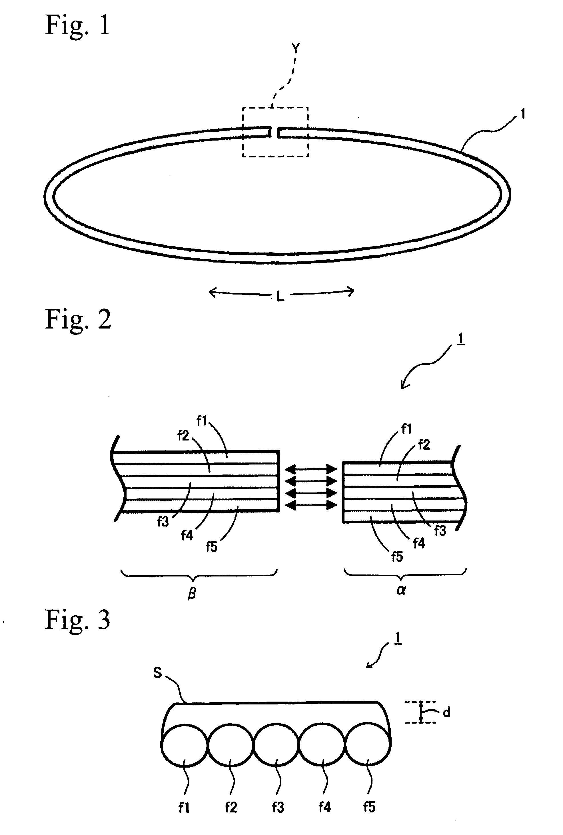
[0096]As single fibers f1 to f5, five single fiber cables having a length of 1.1 meters were used.

[0097]The single fibers f1 to f5 (quartz single-mode optical fiber, outer diameter 0.25 mm, produced by Furukawa Electric Co., Ltd.) were arranged in parallel and were covered on one side thereof by a covering portion S, and thereby an optical fiber ribbon 1 was produced.

[0098]The covering portion S was room-temperature-setting silicone rubber (trade name: TSE392, hardness of 26, tensile strength of 16 kgf / cm2, produced by GE Toshiba Silicones Ltd.). Thickness d of the covering portion was 100 μm.

[0099]A production method for the optical fiber ribbon 1 having one covered side which was made from the single fibers f1 to f5, was as follows. The room-temperature-setting silicone rubber before curing, which was covering material, was applied on the single fibers f1 to f5 arranged in a plane, and then the covering material was molded using a molding jig and was cured by drying.

[0100]The coat...

example 2

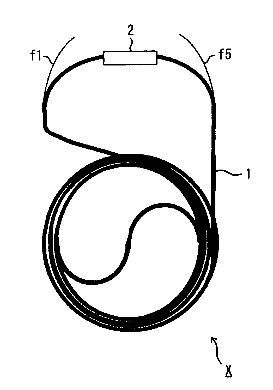
[0106]Next, an optical fiber coil in a bundled state of Example 2 will be explained.

[0107]The optical fiber coils produced in Example 1 were spirally bundled using the above-mentioned winding jig 11, and an optical fiber coil in a bundled state of Example 2 was produced.

[0108]When the optical fiber coils were bundled, an ultraviolet radiation curable adhesive (trade name: viscotack PM-654, produced by Osaka Organic Chemical Industry Ltd.) was applied in advance between the optical fiber coils using a dispenser and was wound, and then it was subjected to an ultraviolet radiation curing (irradiation strength of 20 mW / cm2, irradiation time of 2 minutes) by an ultraviolet irradiation device.

[0109]This optical fiber coil X in a bundled state was constructed of one optical fiber coil in which the length from an end of the optical fiber f1 to an end of the optical fiber f5 was about 5.4 m, and optical transmission loss thereof was about 0.8 dB.

[0110]Since in the optical fiber coil in a bun...

example 3

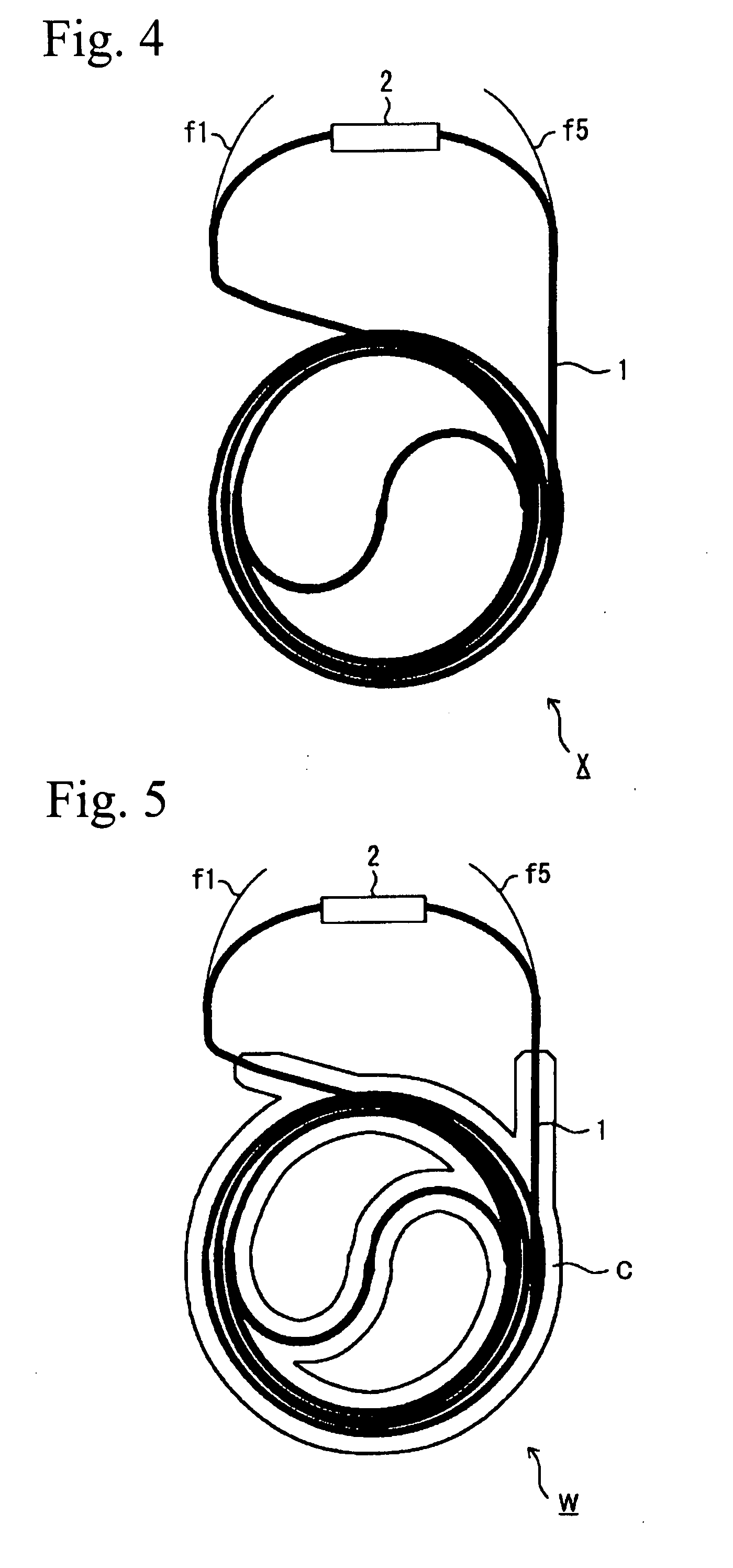
[0111]Next, an optical fiber coil in a bundled state of Example 3 will be explained.

[0112]With respect to the optical fiber coil in a bundled state produced in Example 2, a portion other than the end portions of the optical fiber ribbon was immersed in liquid silicone rubber (trade name: SE 9189 L, produced by Dow Corning Toray Co., Ltd.). The optical fiber coil was pulled out, was dried, and was cured. Therefore, an optical fiber coil W in a bundled state of Example 3 was produced.

[0113]The optical fiber coil W in a bundled state was constructed of one optical fiber coil in which a length from an end of the optical fiber f1 to an end of the optical fiber f5 was about 5.4 m.

[0114]Furthermore, the optical fiber coil W in a bundled state of Example 3 was extremely superior in durability against stress.


PUM


Abstract

An optical fiber coil and a production method therefor make it unnecessary for spaces between single fibers to be widened and for stress to be applied to the single fibers, and in which time and economic costs are low. In the optical fiber coil, an optical fiber ribbon is formed by arranging in parallel plural of single fibers and by integrally covering the single fibers with a covering portion, and ends of the ribbon are connected so that an end of at least one single fiber is connected to an end of another single fiber.

Description

BACKGROUND OF THE INVENTION[0001]1. Field of the Invention[0002]The present invention relates to an optical fiber coil which can be used in a fiber gyro, sensor, optical amplifier, laser, dispersion compensator, nonlinear optical device, delay circuit, dummy circuit, other parts employing long optical fibers, extra long handling tool, etc., and which can be used to conserve space and have low tension, and the present invention also relates to a production method for the optical fiber coil.[0003]2. Description of Related Art[0004]Optical fiber type devices that employ optical fibers therein are widely employed in, for example, sensors. In addition, such optical fiber type devices have attracted attention in optical fiber amplifiers which are doped with erbium, thulium, praseodymium, etc., dispersion compensators using dispersion-compensated optical fiber, and nonlinear optical devices.[0005]It is known that the optical fiber type device is a superior device, that its connectivity wit...

Claims


Application Information

Patent Timeline
Patent Type & Authority Applications(United States)
IPC IPC(8): G02B6/26
CPCG01C19/722G02B6/4457G02B6/08G02B6/38G02B6/26G01C19/72
Inventor SUZUKI, MASAYOSHISASAKI, KYOICHI
Owner TOMOEGAWA CO LTD
Why Eureka
Try Eureka