Circular Polarizer, Process for Producing the Same, Optical Film, Liquid Crystal Display Device and Electroluminescence Device

a technology of circular polarizers and polarizing elements, applied in the direction of polarising elements, instruments, electroluminescent devices, etc., can solve the problems of increasing the thickness of the resulting liquid crystal panel, too low living contrast to be used as a light source for a display device, and poor productivity, so as to reduce the number of layers of the circular polarizer, reduce the number of layers, and reduce the effect of shrinkage strain on each layer

Inactive Publication Date: 2008-05-08
NIPPON OIL CORP
View PDF2 Cites 25 Cited by
  • Summary
  • Abstract
  • Description
  • Claims
  • Application Information

AI Technical Summary

Benefits of technology

[0043] In the present invention, a circular polarizer is produced using an optically anisotropic element as a protection film for a polarizing element. Whereby, the number of the layers constituting the circular polarizer can be reduced than where an optically anisotropic element is attached to a polarizer wherein the both sides of a polarizing element are protected with cellulose triacetate films. As the result, the circular polarizer is less affected by shrinkage strain of each layer caused by heat or humidity and can remove defects such as peeling off at interfaces between the layers. However, it is difficult to adhere an optically anisotropic element only produced by forming a liquid crystal layer on a cellulose triacetate film, to a polarizing element. In the present invention, this is solved by saponifying the optically anisotropic element, thereby making it possible to totally achieve the objects of the present invention.

Problems solved by technology

That is, the organic EL device has crucial problems that it is too low in living contrast to be used as a light source for a display device because it excessively reflects room lighting on its specular surface and thus fails to display black color in a bright place.
However, there are problems that the circular polarizer is increased in thickness by the portion of a tacky adhesive layer used for laminating a polarizer and a retardation film, which tacky adhesive layer will decrease the amount of the circular polarizer per roll when it is rolled up in the form of roll during the production, leading to a poor productivity and will increase the thickness of the resulting liquid crystal panel.
Further, the circular polarizer has disadvantages that peeling off between the interfaces of the polarizer and the retardation film occurs under elevated temperature or humidity conditions because the circular polarizer is constructed by different layers that vary in their expansion and contraction behavior caused by heat or humidity.
More specifically, the degree of freedom of the optical characteristics of the stretch-aligned retardation film is limited because it is difficult to control the alignment of the polymer at will.
Therefore, the production of a circular polarizer by continuously laminating an elongate polarizer and an elongate retardation film is limited to a special case wherein the absorption axis of the polarizer is parallel to the alignment axis of the retardation film.
However, in order to arrange the axes at a cross angle of 45 or 135 degrees, which is other than parallel, the polarizer and the retardation film each in an elongate form must be cut into sheets to be laminated, causing problems that the production steps becomes complicated and the productivity becomes poor.
As described above, a demand to a circular polarizer that has variations in arrangement of the absorption axis of the polarizer and the alignment axis of the retardation film and excellent optical properties has not been met sufficiently.
However, these circular polarizers still had defects as described above, i.e., increased thickness of the polarizers and peeling off at the interface between the polarizer and the optically anisotropic element at elevated temperatures and humidity.

Method used


Image

  • Circular Polarizer, Process for Producing the Same, Optical Film, Liquid Crystal Display Device and Electroluminescence Device
  • Circular Polarizer, Process for Producing the Same, Optical Film, Liquid Crystal Display Device and Electroluminescence Device
  • Circular Polarizer, Process for Producing the Same, Optical Film, Liquid Crystal Display Device and Electroluminescence Device

Examples


reference example 1

[0118] Among optical retardation films (twisted optical retardation films) with twisted structures each having a twisted angle and a retardation as parameters, films having such parameters that they can function as a circular polarizer in combination with a polarizer were sought. Since in a laminate composed of a polarizer, a twisted optical retardation film, and a mirror, the rotation direction of a circularly polarized light is reversed when it is reflected at the mirror surface, the reflectance of a light made incident vertically to the mirror from the polarizer side is ideally zero. Using this principle, in a laminate comprised of a polarizer, a twisted optical retardation film, and a mirror, the combinations of parameters such as the absorption axis direction of the polarizer and the twisted angle and retardation of the optical retardation film are calculated with an extended Jones matrix method. From the results of the calculation, the reflectance was evaluated with “Y” value ...

example 1

Preparation of Polymer Solution A

[0122] A polymerization was carried out using 50 mmole of terephthalic acid, 50 mmole of 2,6-naphthalene dicarboxylic acid, 40 mmole of methylhydroquinone diacetate, 60 mmole of catechol diacetate, and 60 mg of N-methylimidazole under a nitrogen atmosphere at a temperature of 270° C. for 12 hours. The resulting reaction product was dissolved in tetrachloroethane and then purified by reprecipitating with methanol thereby obtaining 14.7 g of a liquid crystalline polyester. It was found that this liquid crystalline polyester (polymer 1) had an inherent viscosity of 0.17 (dl / g), a nematic liquid crystalline phase, an isotropic phase-liquid crystalline phase transition temperature of 250° C. or higher, and a glass transition temperature of 115° C.

[0123] In dichloromethane, 90 mmol of biphenyldicarbonylchloride, 10 mmol of terephthaloylchloride, 105 mmol of S-2-methyl-1,4-butanediol were reacted at room temperature for 20 hours, and the reaction solution...

example 2

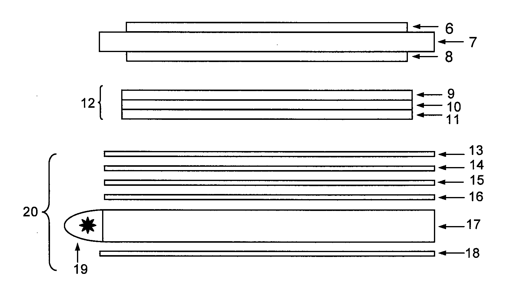
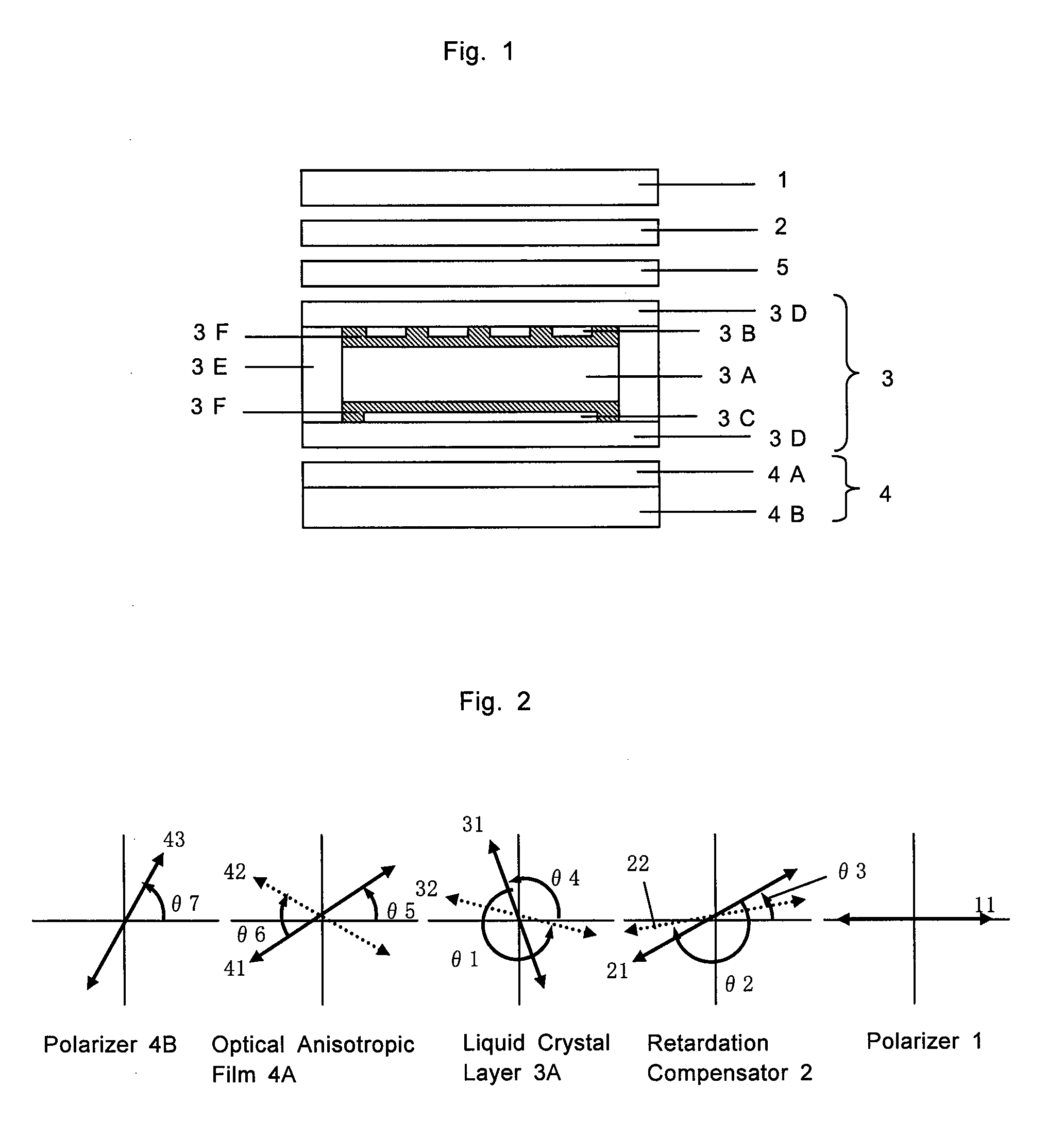
[0127] A transflective STN liquid crystal display with a structure as shown in FIG. 1 was produced using the circular polarizer produced in Example 1. In this example, the experiments were conducted using a liquid crystal cell wherein the counterclockwise direction from the polarizer 1 to the liquid crystal cell 3 was defined as “+”, while the clockwise direction was defined as “−”. However, the same results were obtained using a liquid crystal cell wherein the counterclockwise direction was defined as “−”, while the clockwise direction was defined as “+”.

[0128] As shown in FIG. 1, a liquid crystal cell 3 is provided with a pair of substrates 3D facing each other, an upper electrode 3B formed on the lower surface of the upper substrate, a transflective electrode 3C formed on the upper surface of the lower substrate, and alignment layers 3F printed on each electrode and having been subjected to an alignment treatment. A liquid crystal layer 3A was formed by injecting a liquid crysta...


PUM

PropertyMeasurementUnit
thicknessaaaaaaaaaa
thicknessaaaaaaaaaa
thicknessaaaaaaaaaa

Abstract

A circular polarizer includes at least an optically anisotropic element, a transmissive protection film and a polarizing element sandwiched therebetween. The optically anisotropic element has a liquid crystal layer aligned on a cellulose triacetate film and a retardation of approximately ¼ wavelength in the visible light region. The liquid crystal layer includes a liquid crystal film with a fixed twisted nematic alignment. The circular polarizer is suppressed in thickness by simplifying the layer structure without causing defects, such as peeling off the layers, even under elevated temperature and humidity condition and makes it possible to set arbitrarily the angle of the alignment axis direction of the optically anisotropic element including a liquid crystal layer with a fixed twisted alignment with respect to the absorption axis of the polarizing element, so that the optically anisotropic element and polarizing element both in the form of an elongate film can be laminated continuously to one another.

Description

CROSS-REFERENCE TO RELATED APPLICATIONS [0001] This application is a continuation of International Application No. PCT / JP2006 / 311465, filed Jun. 1, 2006, which was published in the Japanese language on Dec. 28, 2006, under International Publication No. WO 2006 / 137268 A1, the disclosure of which is incorporated herein by reference.BACKGROUND OF THE INVENTION [0002] The present invention relates to circular polarizers comprising a liquid crystal film with a fixed twisted nematic alignment, processes for producing such circular polarizers, optical films comprising such circular polarizers and further to liquid crystal display devices comprising such circular polarizers or optical films and electroluminescence devices (hereinafter referred to as “EL device”) used in self-luminous flat display devices as well as in various illuminants or lighting units, in particular organic EL devices with excellent visibility, comprising such circular polarizers or optical films. [0003] Circular polari...

Claims


Application Information

Patent Timeline
Patent Type & Authority Applications(United States)
IPC IPC(8): G02B5/30G02F1/13363
CPCG02B5/3016G02B6/0056G02B27/286H01L51/5293G02F1/13363G02F2001/133541G02F1/133528G02F1/133541H10K50/868G02F1/1335G02B5/30
Inventor UESAKA, TETSUYANISHIMURA, SUZUSHI
Owner NIPPON OIL CORP
Why Eureka
Try Eureka