Fuel-Cell Stack And Fuel Cell

Active Publication Date: 2008-05-15
PANASONIC CORP
View PDF11 Cites 26 Cited by
  • Summary
  • Abstract
  • Description
  • Claims
  • Application Information

AI Technical Summary

Benefits of technology

[0030]According to the present invention, in a fuel-cell stack in which a first cell and a second cell are stacked, elongation variations among the cells of the gas-diffusion-layer base material that forms the gas diffusion layer of either one electrode of the anode or the cathode in each cell are limited to within ±30% with respect to a direction perpendicular to the primary direction of the gas flow passages of the separators. Therefore, it becomes achievable to reduce variations am

Problems solved by technology

As a result, in cells of smaller gas flow rates, there is a problem of occurrence of a voltage instability phenomenon (flooding) that water droplets block the gas flow passage, causing deficiencies of fuel supply to the electrode and the cataly

Method used


Image

  • Fuel-Cell Stack And Fuel Cell
  • Fuel-Cell Stack And Fuel Cell
  • Fuel-Cell Stack And Fuel Cell

Examples


example 1

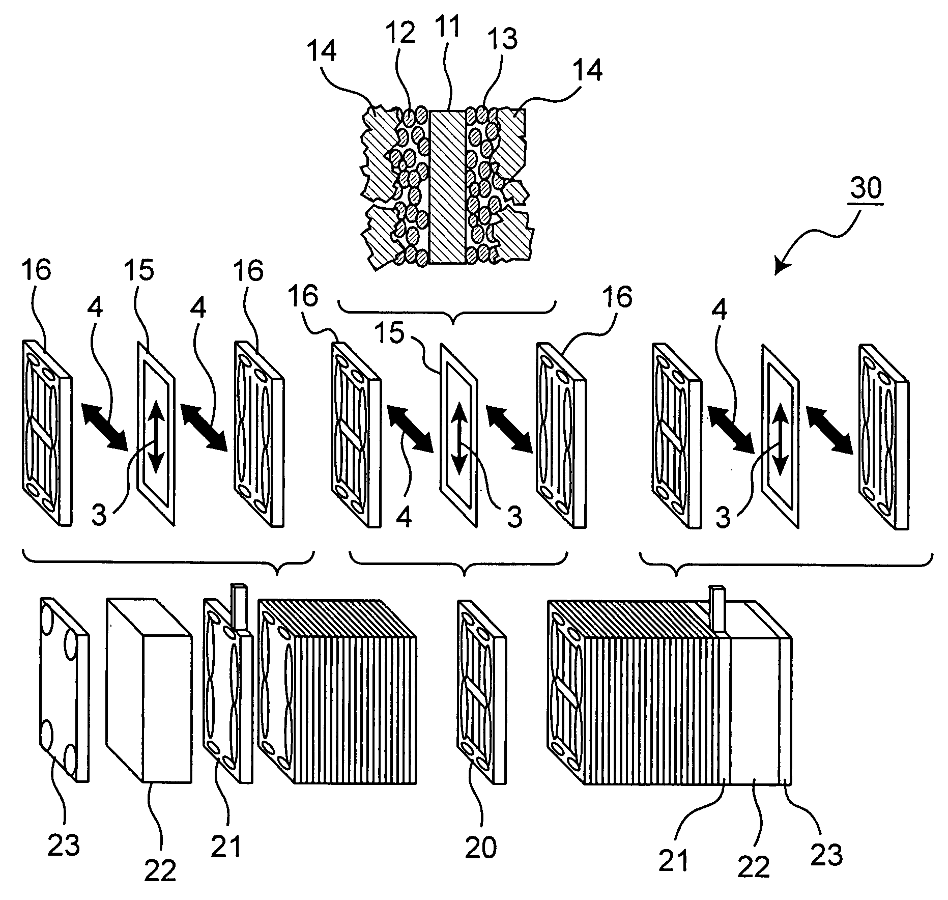
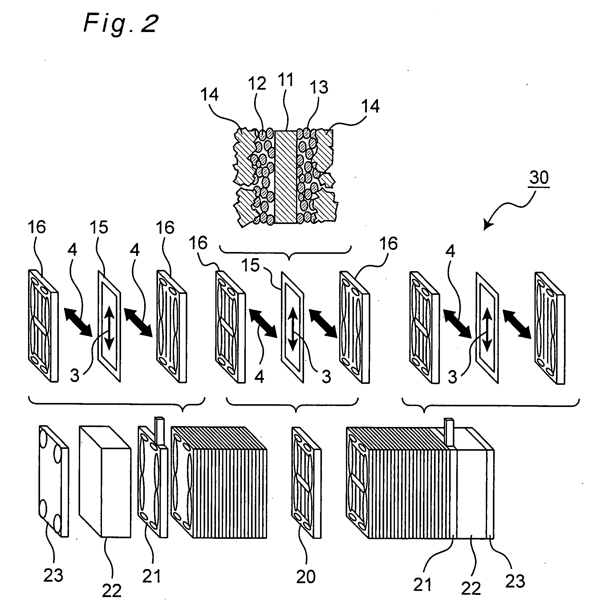
[0087]First, a method for fabricating an MEA included in a fuel-cell stack according to Example 1 of the invention is explained. Both sides of a polyelectrolyte membrane (Nafion 112 made by DuPont) were coated with a catalyst in which platinum was carried on acetylene black powder, by which a catalytic layer was formed. Further on outer surfaces of the catalytic layer, a gas diffusion layer formed with a base material of carbon fiber woven cloth was placed. The carbon fiber woven cloth was of plain weave, and GDL-1 (gas-diffusion-layer base material-1) shown in Table 2 was used therefor.

[0088]It is noted that Table 2 shows characteristic data on elongations of two kinds of gas-diffusion-layer base materials, GDL-1 and GDL-2, of different characteristics. An elongation (%) is expressed in value from a calculation that a displacement amount of carbon fiber woven cloth at a load 10N resulting from application of a tensile load to a 25 mm wide carbon fiber woven cloth with a chuck-to-ch...

example 2

[0097]Next, a fuel-cell stack according to Example 2 is described. An MEA and a separator were fabricated in the same manner as in Example 1, and a unit cell was fabricated in such a placement that the placement direction of warp of the carbon fiber woven cloth GDL-1 shown in Table 2 would be perpendicular to the primary direction of the gas flow passages of the separator. As in Example 1, this unit cell was stacked to a quantity of 50 cells, and a stainless current-collector plate, an insulating plate made of an electrical insulating material and an end plate were placed on each of the two end portions, all of these members being fixed by a tightening rod, by which a fuel-cell stack was fabricated. That is, in Example 2, a stack in which the gas-diffusion-layer base material (GDL-1) was so placed that elongation variations with respect to the direction perpendicular to the primary direction of the gas flow passages would fall within ±18% as shown in Table 2 was fabricated.

[0098]A p...

example 3

[0099]Next, a fuel-cell stack according to Example 3 is described. An MEA and a separator were fabricated in the same manner as in Example 1, and a unit cell was fabricated in such a placement that the placement direction of warp of the carbon fiber woven cloth GDL-2 shown in Table 2 would be parallel to the primary direction of the gas flow passages of the separator.

[0100]As in Example 1, this unit cell was stacked to a quantity of 50 cells, and a stainless current-collector plate, an insulating plate made of an electrical insulating material and an end plate were placed on each of the two end portions, all of these members being fixed by a tightening rod, by which a fuel-cell stack was fabricated. That is, in Example 2, a stack in which the gas-diffusion-layer base material (GDL-2) was so placed that elongation variations with respect to the direction perpendicular to the primary direction of the gas flow passages would fall within ±20% as shown in Table 2 was fabricated.

[0101]A p...


PUM


Abstract

In a fuel-cell stack in which a plurality of cells are stacked, each of the cells including a membrane electrode assembly which is composed of a polyelectrolyte membrane and a pair of electrodes sandwiching the polyelectrolyte membrane, and a pair of separators by which the membrane electrode assembly is sandwiched, where the electrodes each have a catalytic layer brought into contact with the polyelectrolyte membrane and a gas diffusion layer brought into contact with the separator, and where a material of the gas diffusion layers is formed from carbon fiber woven cloth. In this fuel-cell stack, the warp direction and weft direction of the carbon fiber woven cloth are so set as to be uniform in all the cells with respect to the primary direction of the gas flow passages of the separators.

Description

TECHNICAL FIELD[0001]The present invention relates to a fuel cell, as well as a fuel-cell stack, which directly uses, as its fuel, pure hydrogen or modified hydrogen derived from fossil fuels or the like, or liquid fuels such as methanol and ethanol, and which uses air or oxygen as its oxidizer. In particular, the invention relates to a PEFC (Polymer Electrolyte Fuel Cell).BACKGROUND ART[0002]A fuel cell, e.g. PEFC, acts to make a hydrogen-containing fuel gas and an oxygen-containing oxidizer gas such as air electrochemically react with each other to produce electric power and heat concurrently. With regard to its structure, first, a catalytic reaction layer mainly composed of carbon powder carrying thereon a platinum-based metal catalyst is formed on both surfaces of a polyelectrolyte membrane which selectively transports hydrogen ions. Next, a gas diffusion layer having both gas permeability and electron conductivity is formed on an outer surface of the catalytic reaction layer. T...

Claims


Application Information

Patent Timeline
IPC IPC(8): H01M8/10H01M4/94H01M8/24
CPCH01M4/8636H01M8/0234Y02E60/50H01M8/241H01M8/0258H01M8/0263H01M8/0267H01M8/2457H01M8/2483
Inventor KAWASHIMA, TSUTOMUOSUMI, TOSHIMASATERANISHI, MASATOSHISUKAWA, TORU
Owner PANASONIC CORP
Why Eureka
Try Eureka