
Charged Particle Beam Orbit Corrector and Charged Particle Beam Apparatus

a charge beam and orbit corrector technology, applied in the field of orbit correction apparatus for a charged particle beam optical system, and a charge particle beam apparatus, can solve the problems of insufficient increase of current acquired, large drawback of method, and great technical difficulty or cost disadvantage, and achieve the effect of low cost, high degree of general versatility, and compact structur

Active Publication Date: 2008-05-22
HITACHI HIGH-TECH CORP
View PDF23 Cites 27 Cited by
  • Summary
  • Abstract
  • Description
  • Claims
  • Application Information

AI Technical Summary

Benefits of technology

[0010]An object of the present invention is to provide a low-cost, high-precision, high-resolution optical converging system for a charged particle beam by solving the problems inherent in a conventional aberration correction system for a rotationally symmetrical system.
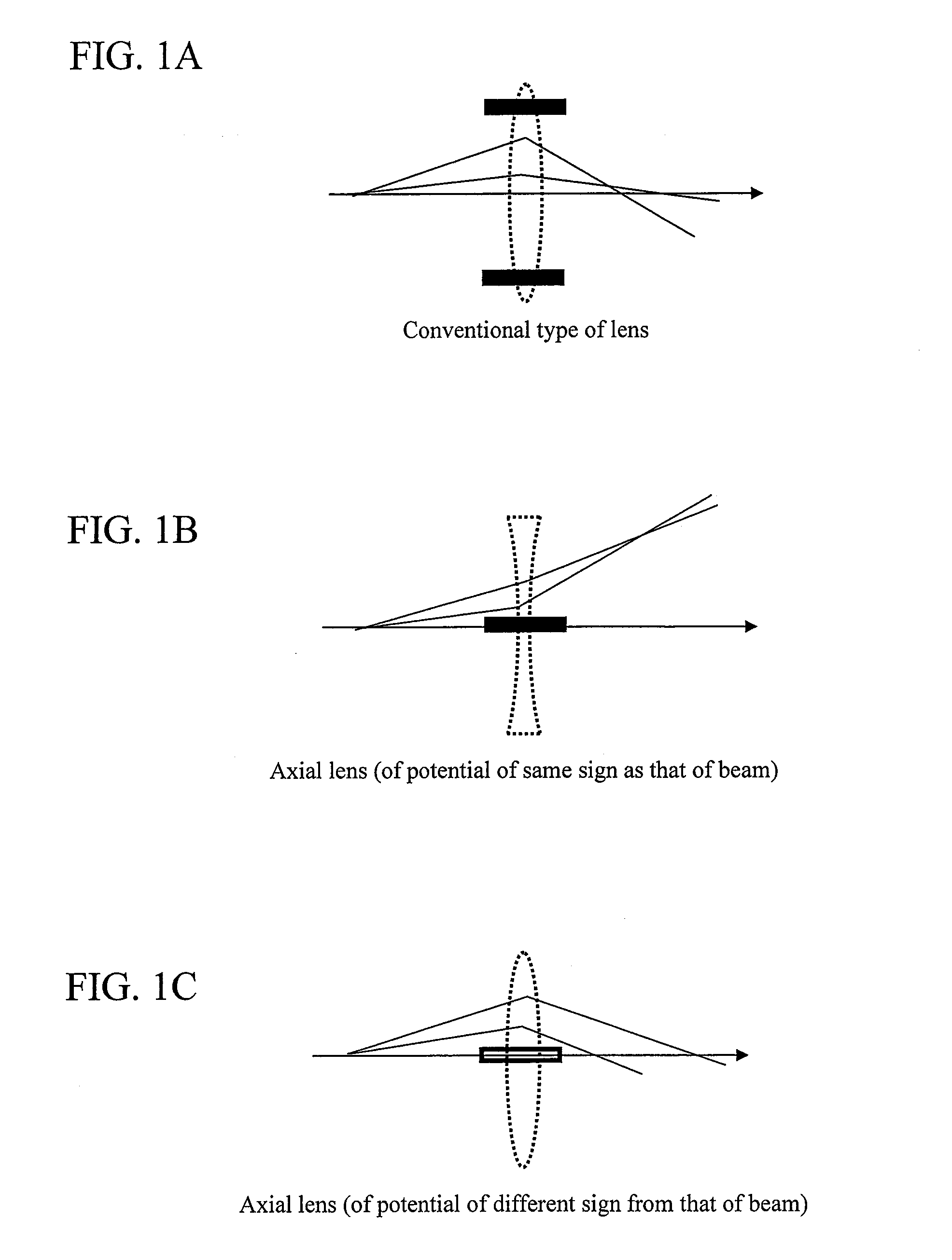
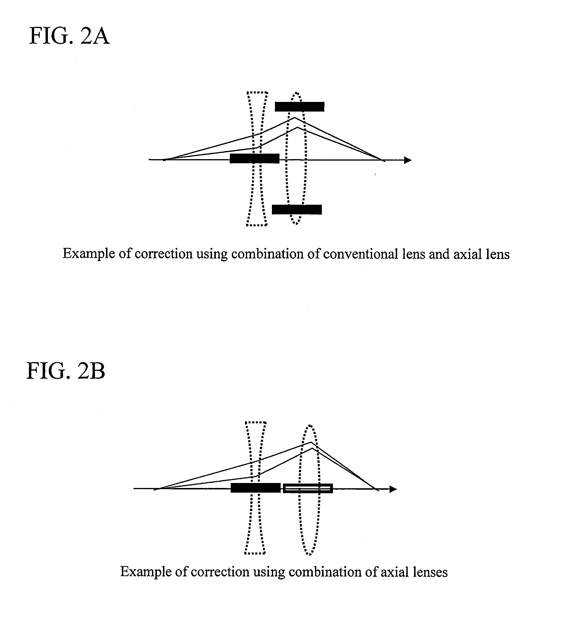
[0013]Specifically, for an electric field, a microelectrode in needle or point form is disposed on the axis to apply a voltage, thereby enabling electrostatic focusing. For a magnetic field, a toroidal coil radially distributed-wound is formed in close proximity to the central axis, thereby enabling a magnetic flux density to converge toward the central axis under the influence of an angular divergence between the coils and a coil winding distribution. These actions can be utilized to cancel out aberration, thus virtually increase the range of radiation angles of a transmitted beam, and thus achieve a desired large current.
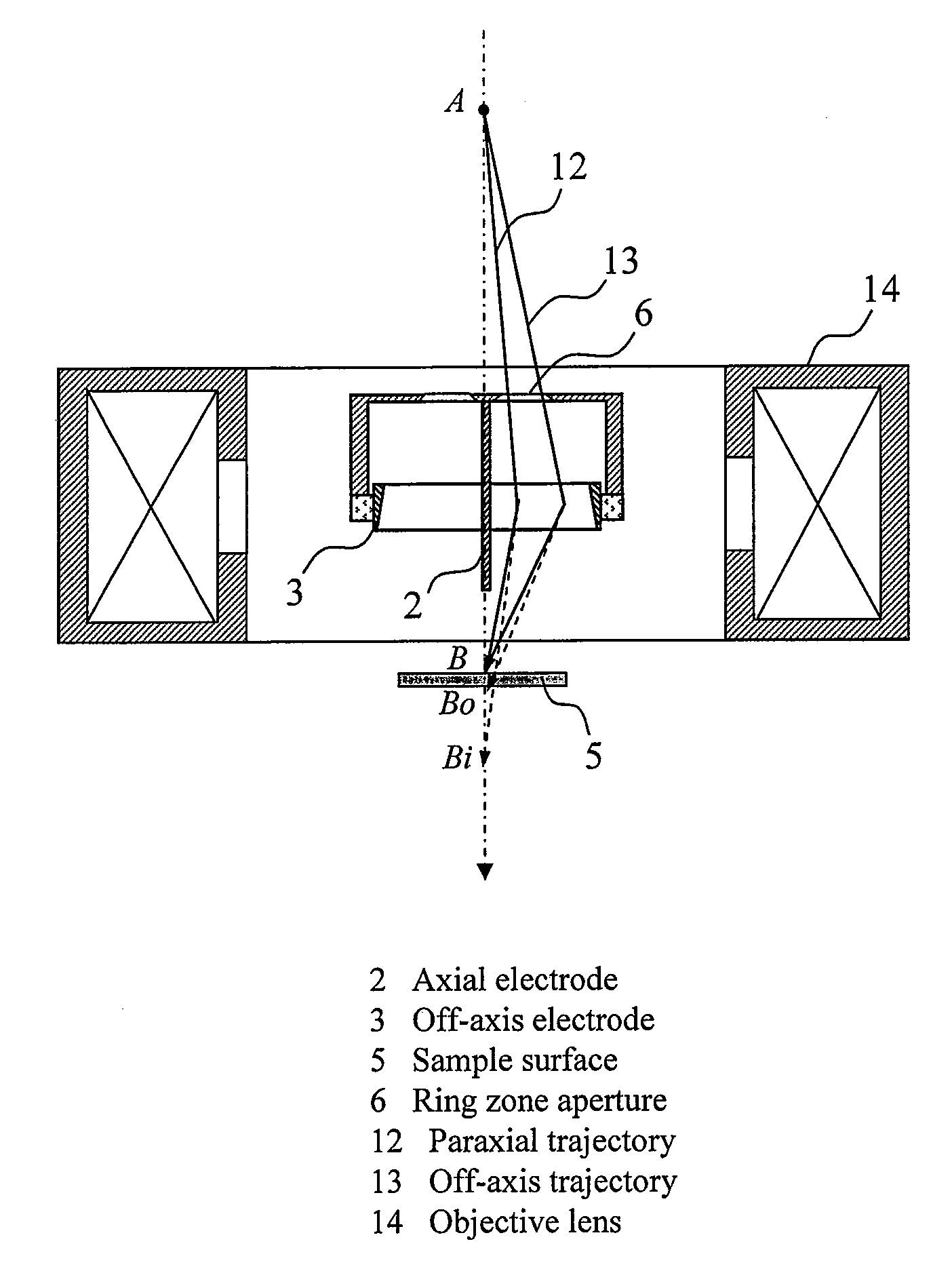
[0018]However, the needle electrode or the long cylindrical electrode increases the likelihood of higher-order aberration occurring depending on a divergent angle of an incoming beam, because of producing a very intense electric field on the axis and in its vicinity as shown in FIGS. 4A to 4C. As opposed to this, the point electrode, although increasing also electrostatic focusing, can reduce aberration, provided that admitted beam orbits are limited, that a support is grounded and sealed, or that plural point electrodes are installed. Further, the corrector may be specifically configured to be provided with an aperture in ring zone form and thereby input and control a beam within an appropriate range of deflecting action distribution shown in FIGS. 4A to 4C.
[0020]Recently, advances in processing technology such as MEMS (Micro-Electro-Mechanical Systems) have enabled microfabrication of an electron source and an electron lens. According to an electro-optical similarity principle, it is known that the electric field type can obtain the same beam orbit when a voltage and an electrode are equally scaled down. Accordingly, the ability to fabricate an electrode of the order of a few tens of micrometers (μm) by use of these microfabrication technologies makes it possible to perform beam orbit control under a low-voltage power supply merely by the replacement of a conventional limiting aperture by the corrector of the present invention.
[0021]Consequently, the present invention can provide an aberration correction method having a high degree of general versatility, extremely compactly, at low cost, with a power supply included therein.

Problems solved by technology

A multipolar correction system or a lens array system is still applied only to some electron microscopes or an electron beam exposure system at the prototyping stage, because of requiring extremely highly accurate machining, disposition, power supply and adjusting method and thus having a great technical difficulty or cost disadvantage.
Moreover, although a ring zone lighting method can be expected to reduce aberration by a given amount and also increase the amount of current, the method has the problem of insufficiently increasing the amount of current acquired particularly in a region not dominated by the space-charge effect, because of capturing an off-axis orbit limited by the aberration.
Due to this, the method has the drawback of being greatly affected by the influence of higher-order aberration.

Method used


Image

  • Charged Particle Beam Orbit Corrector and Charged Particle Beam Apparatus
  • Charged Particle Beam Orbit Corrector and Charged Particle Beam Apparatus
  • Charged Particle Beam Orbit Corrector and Charged Particle Beam Apparatus

Examples


Embodiment Construction

[0040]Embodiments of the present invention will be described below. Although description will hereinafter be given with regard to an instance where an electron is used as a charged particle, a corrector of the present invention may be applied to an instance where an ion is used as the charged particle.

[0041]FIGS. 6A and 6B and FIGS. 7A and 7B show examples of electric field type correctors having axial electrodes formed of a needle electrode type and a point electrode type, respectively.

[0042]FIGS. 6A and 6B are views showing an example of the prior-art electric field type corrector having the axial electrode in needle form. FIG. 6A is a plan view, and FIG. 6B is a cross-sectional view taken along the line B-B of FIG. 6A. In the example of the prior-art electric field type corrector, an axial electrode 2 is disposed as suspended by a support 7 along the central axis of an off-axis electrode 3. The off-axis electrode 3 is externally fixed by the support 7, and a voltage Vout can be a...


PUM


Abstract

The present invention relates to an orbit correction method for a charged particle beam, and aims to solve problems inherent in conventional aberration correction systems and to provide a low-cost, high-precision, high-resolution optical converging system for a charged particle beam. To this end, employed is a configuration in which a beam orbit is limited in ring zone form to form a distribution of electromagnetic field converging toward the center of a beam orbit axis. Consequently, a nonlinear action outwardly augmented, typified by spherical aberration of an electron lens, can be cancelled out. Specifically, this effect can be achieved by an electron disposed on the axis and subjected to a voltage to facilitate the occurrence of electrostatic focusing. For a magnetic field, this effect can be achieved by forming a coil radially distributed-wound on a surface equiangularly divided in the direction of rotation to control convergence of a magnetic flux density.

Description

CLAIM OF PRIORITY[0001]The present application claims priority from Japanese application JP 2006-313816 filed on Nov. 21, 2006, the content of which is hereby incorporated by reference into this application.BACKGROUND OF THE INVENTION[0002]1. Field of the Invention[0003]The present invention relates to an orbit correction apparatus for a charged particle beam optical system, and a charged particle beam apparatus, such as an electron microscope, having the same.[0004]2. Description of the Related Art[0005]A charged particle beam apparatus plays an important role in a wide field of nanotechnology. The charged particle beam apparatuses include a scanning electron microscope (SEM) that scans a focused beam of electrons over the surface of a sample, detects signal electrons from the surface of the sample, and makes the detected signal visible on an image display device; a transmission electron microscope that allows electrons to pass through a sample and focuses the diverging electrons t...

Claims


Application Information

Patent Timeline
IPC IPC(8): G21K1/087G21K1/093
CPCH01J37/09H01J37/12H01J37/141H01J2237/303H01J37/28H01J2237/142H01J2237/1534H01J37/153
Inventor ITO, HIROYUKISASAKI, YUKOISHITANI, TOHRUNAKAYAMA, YOSHINORI
Owner HITACHI HIGH-TECH CORP
Learn More