Optical alignment method and liquid crystal display element

a liquid crystal display element and optical alignment technology, applied in non-linear optics, optics, instruments, etc., can solve the problems of reducing the contrast and productivity of the liquid crystal display element, deteriorating the display quality, and destroying the active element of the tft element,

Inactive Publication Date: 2008-05-29
JSR CORPORATIOON +1
View PDF15 Cites 6 Cited by
  • Summary
  • Abstract
  • Description
  • Claims
  • Application Information

AI Technical Summary

Benefits of technology

[0009]It is an object of the present invention to provide a novel optical alignment method which can solve the above problems.
[0010]It is another object of the present invention to provide an optical alignment method which eliminates the need for the inclination of a substrate in the method of developing a pretilt angle in the optical alignment method and develops a pretilt angle by batch plane exposure.
[0011]It is still another object of the present invention to provide an optical alignment method which eliminates the need for the inclination of a substrate in the method of developing a pretilt angle in the optical alignment method and develops a pretilt angle large enough to be used in a homeotropic alignment mode by batch plane exposure.

Problems solved by technology

However, since the surface of an alignment film is directly rubbed with cloth, the alignment film is chipped or static electricity is generated by rubbing.
When the alignment film is chipped, dust is produced or the surface of the alignment film is scratched, thereby causing the marked deterioration of display quality when the above multiplex drive type liquid crystal display element is turned on.
In the active drive type liquid crystal display element, the generation of static electricity leads to the destruction of a TFT element as an active element.
In either case, rubbing causes reductions in the contrast and productivity of the liquid crystal display element.
(1) An error in the setting of the angle of the substrate causes a great variation in pretilt angle.
(2) Since the substrate is inclined, irradiation energy varies within the plane, which causes a variation in pretilt angle within the plane.
(3) In the case of oblique exposure, the pretilt angle is changed by the complicated secondary influences of light first applied to the optical alignment layer and reflected light produced while the above light passes through the layer.
(4) When the method of FIG. 1 is used with an oblique exposure device and, for example, a 1 m×1 m glass substrate is inclined at 45° from the horizontal direction, the height of the glass storage section of the exposure device must be 50 cm or more, thereby greatly increasing the size of the device.
(5) When the method of FIG. 2 is used with an oblique exposure device, it is very difficult in the design of the exposure device to change the irradiation angle arbitrarily while a 1 m×1 m exposure area is ensured. That is, the structure of the exposure device becomes complex by making variable the irradiation angle of ultraviolet radiation in the exposure device due to the control of the optical axis of an optical element and the like.
(6) It is difficult to develop a pretilt angle large enough to be used in a homeotropic alignment mode.

Method used


Image

  • Optical alignment method and liquid crystal display element
  • Optical alignment method and liquid crystal display element
  • Optical alignment method and liquid crystal display element

Examples


example 1

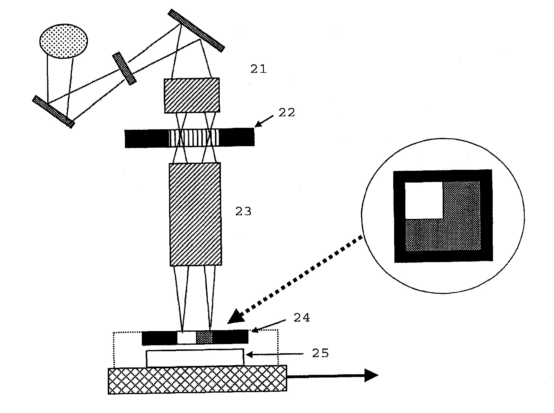
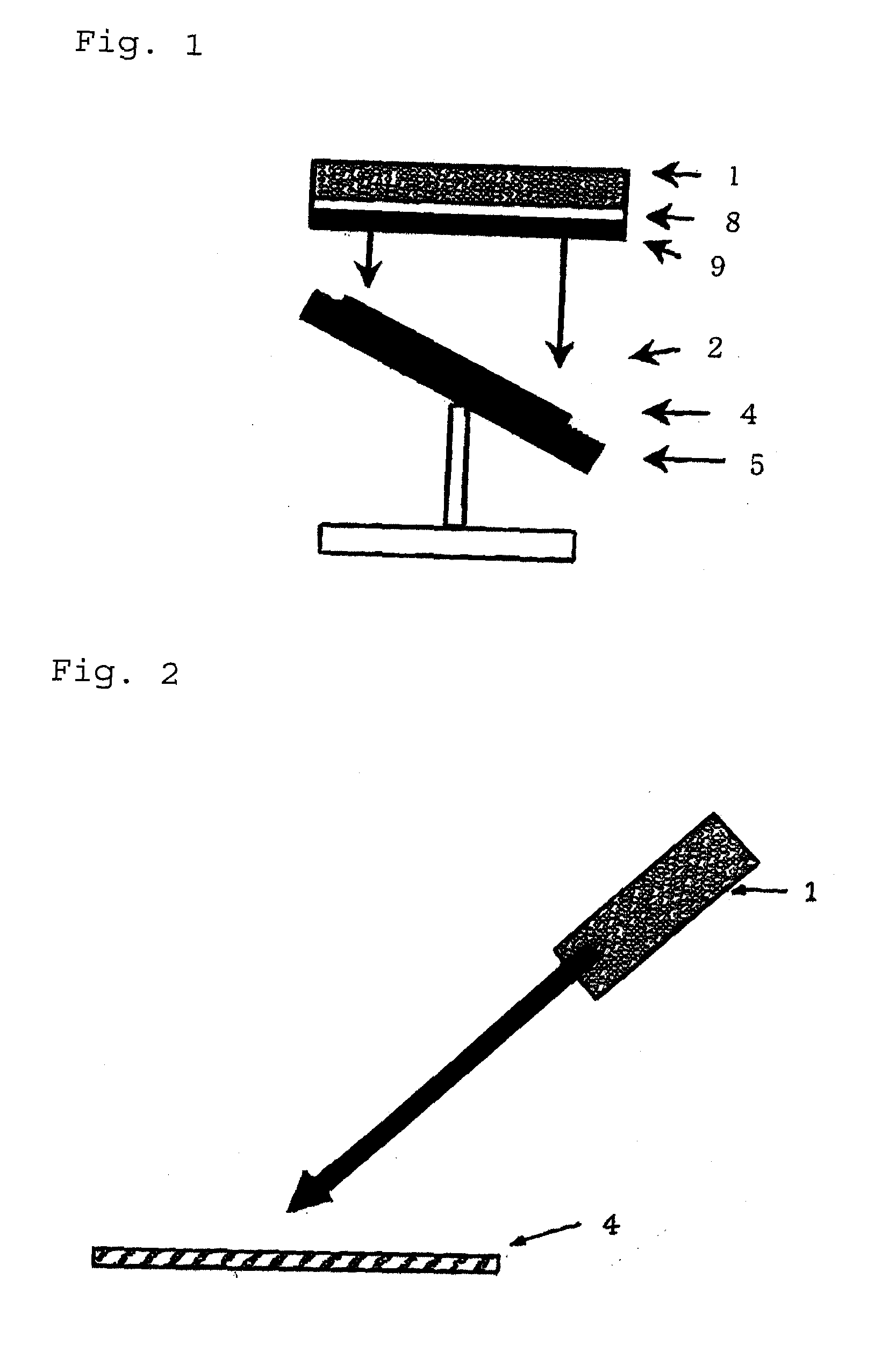
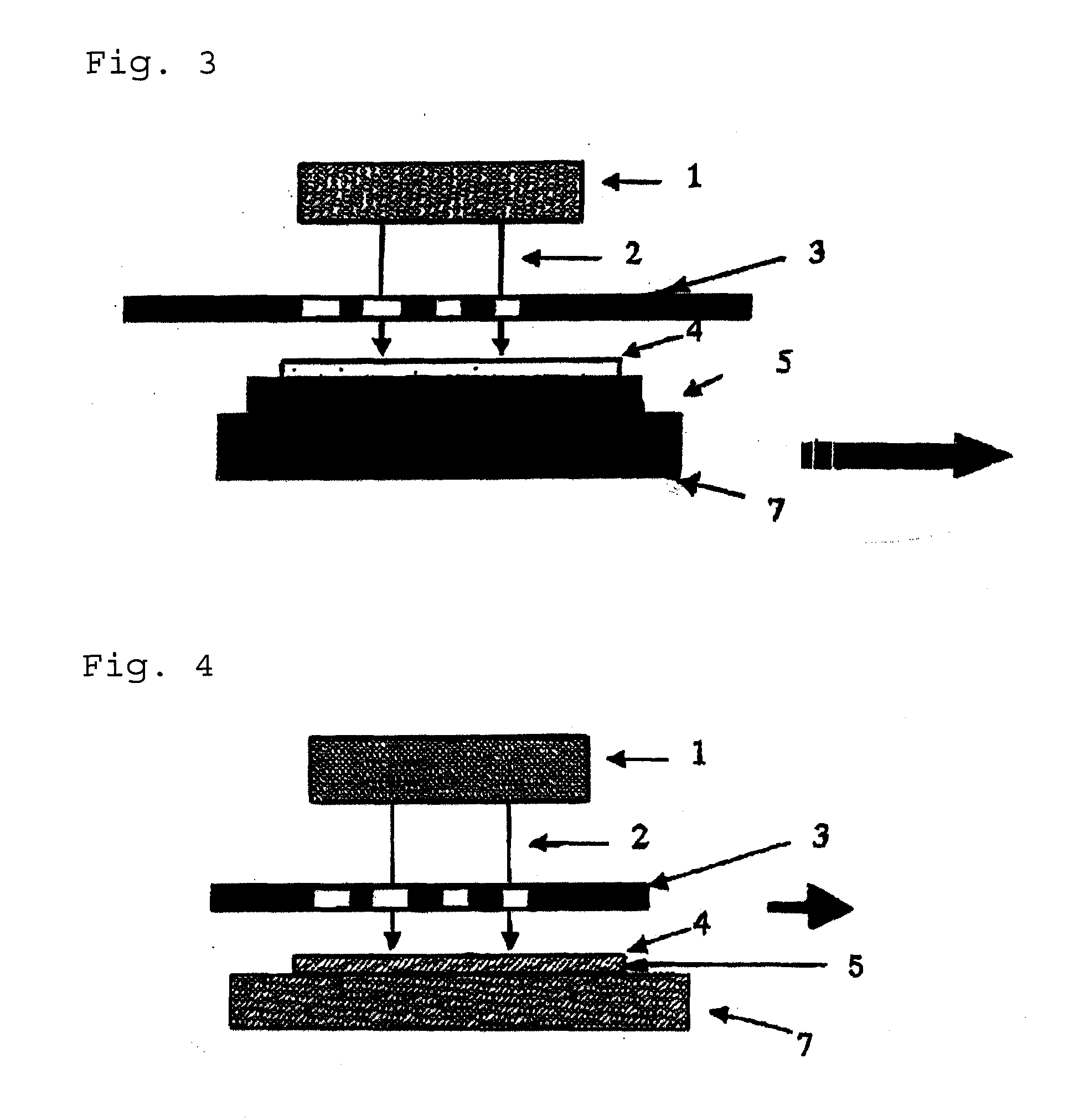
[0263]Optical alignment was carried out as shown in FIG. 3.

[0264]A polymer (may be called to “PMI-15” hereinafter) prepared by introducing a chalcone group as a side chain into a phenylmaleimide-styrene alternating copolymer through a methylene group was dissolved in γ-butyrolactone in an amount of 3%, and the obtained solution was applied to a quartz glass substrate 5 by spin coating and dried to form a polymer film having a thickness of 70 nm. Thereafter, the surface of the polymer film was exposed to polarized UV having a central wavelength of 350 nm from a polarization irradiating unit 1 through a slit exposure mask 3 while a movable stage 6 mounting the formed substrate was moved parallel to the X-axis direction (right direction) at a rate of several tens of micrometers per second so as to exposure the slit pattern. The irradiation energy was 2 J / cm2. A slit exposure mask pattern having line and space widths of 7 μm as shown in FIG. 7 was used in this example. Thereafter, two e...

synthesis example 1

Polymerization of Polyamic Acid

[0268]0.1 mol (22.4 g) of 2,3,5-tricarboxycyclopentylacetic dianhydride, 0.09 mol (9.73 g) of p-phenylenediamine and 0.01 mol (5.22 g) of cholestanyloxy(3,5-diaminobenzoyl) were dissolved in 350 g of N-methyl-2-pyrrolidone and reacted at 60° C. for 6 hours. Thereafter, the reaction mixture was added to an excessive amount of methanol to precipitate a reaction product. The precipitate was then washed with methanol and dried at 40° C. under reduced pressure for 15 hours to produce 34.2 g of polyamic acid (to be referred to as “polymer a” hereinafter).

Synthesis of Specific Polymer

[0269]300 g of N-methyl-2-pyrrolidone, 41.3 g of 1-bromo-8-(4-chalconyloxy)octane and 13.8 g of potassium carbonate were added to 14.9 g of the obtained polymer a to carry out a reaction at 120° C. for 4 hours. Thereafter, the reaction mixture solution was added to water to precipitate a reaction product. The obtained precipitate was washed with water and dried under reduced pres...

example 2

[0270]The polymer “b” obtained in Synthesis Example 1 was dissolved in γ-butyrolactone to prepare a 3 wt % solution, and the obtained solution was applied to a surface polished non-alkali glass substrate by spin coating and dried by heating at 180° C. for 5 minutes to form a polymer film having a thickness of 80 nm. The surface of the polymer film was exposed to polarized UV having a central wavelength of 350 nm through a slit exposure mask while a movable stage mounting the substrate was moved parallel to the surface of the polymer film at a rate of 100 μm / sec. The irradiation energy was 5 J / cm2, and the polarization direction of the polarized UV was the same as the moving direction. The slit width of the exposure mask was 7 μm. Thereafter, the exposed substrate was used to construct a non-parallel cell having a thickness of 18 μm, and the MLC6608 liquid crystals of Merk Co., Ltd. were filled to obtain a liquid crystal display element. The alignability of the liquid crystals was ex...


PUM

PropertyMeasurementUnit
speedaaaaaaaaaa
wavelengthaaaaaaaaaa
pretilt angleaaaaaaaaaa

Abstract

An optical alignment method which develops a pretilt angle by batch plane exposure without tilting a substrate. This optical alignment method provides liquid crystal aligning capability to the surface of a polymer film by exposing the surface of the polymer film through a slit exposure mask while the surface of the polymer film and the slit exposure mask are moved relative to each other substantially at a fixed rate. Alternatively, liquid crystal aligning capability is provided to the surface of the polymer film by exposing the surface of the polymer film through an optical exposure pattern while the optical exposure pattern having a plurality of lines with a certain width at certain intervals is formed on the surface of the polymer film continuously.

Description

FIELD OF THE INVENTION[0001]The present invention relates to an optical alignment method and to a liquid crystal display element formed by the same.DESCRIPTION OF THE RELATED ART[0002]Liquid crystal display elements are widely used in monitors for notebook personal computers and image display devices for portable telephones and portable information terminals.[0003]The liquid crystal display elements are divided into (1) display type liquid crystal elements in which pixels are turned on and off by optical switching through the selective application of a voltage to liquid crystal molecules on a desired electrode formed in the pixels after a panel having a large number of pixels is constructed by sandwiching a liquid crystal material between glass substrates at least one of which has a transparent electrode formed thereon and (2) display type liquid crystal elements in which desired pixels are turned on and off by selecting an active element after a liquid crystal panel is constructed ...

Claims


Application Information

Patent Timeline
Patent Type & Authority Applications(United States)
IPC IPC(8): G02F1/13G02F1/1337
CPCG02F2001/133742G02F1/133788G02F1/133742G02F1/1337
Inventor KIMURA, MASAYUKIYOKOYAMA, HIROSHI
Owner JSR CORPORATIOON
Why Eureka
Try Eureka