
Microinjection devices and methods of use

a micro-injection device and micro-injection technology, applied in the field of micro-injection devices and methods of use, can solve the problems of retrovirus use, inefficiency and time-consuming production of transgenic chickens by means of dna micro-injection, and limitations of transgene siz

Inactive Publication Date: 2008-05-29
SYNAGEVA BIOPHARMA CORP
View PDF28 Cites 56 Cited by
  • Summary
  • Abstract
  • Description
  • Claims
  • Application Information

AI Technical Summary

Benefits of technology

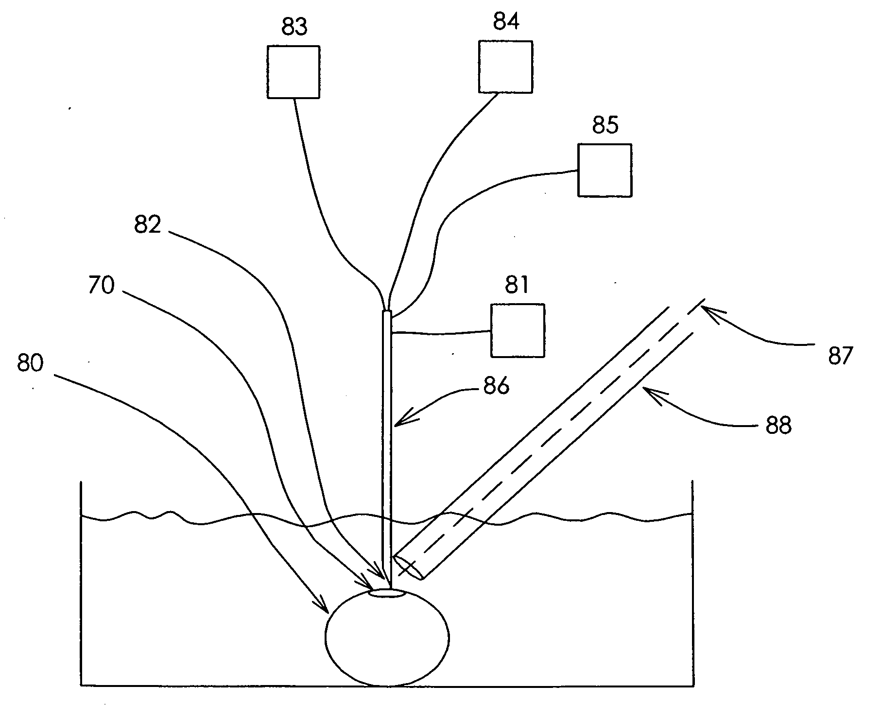
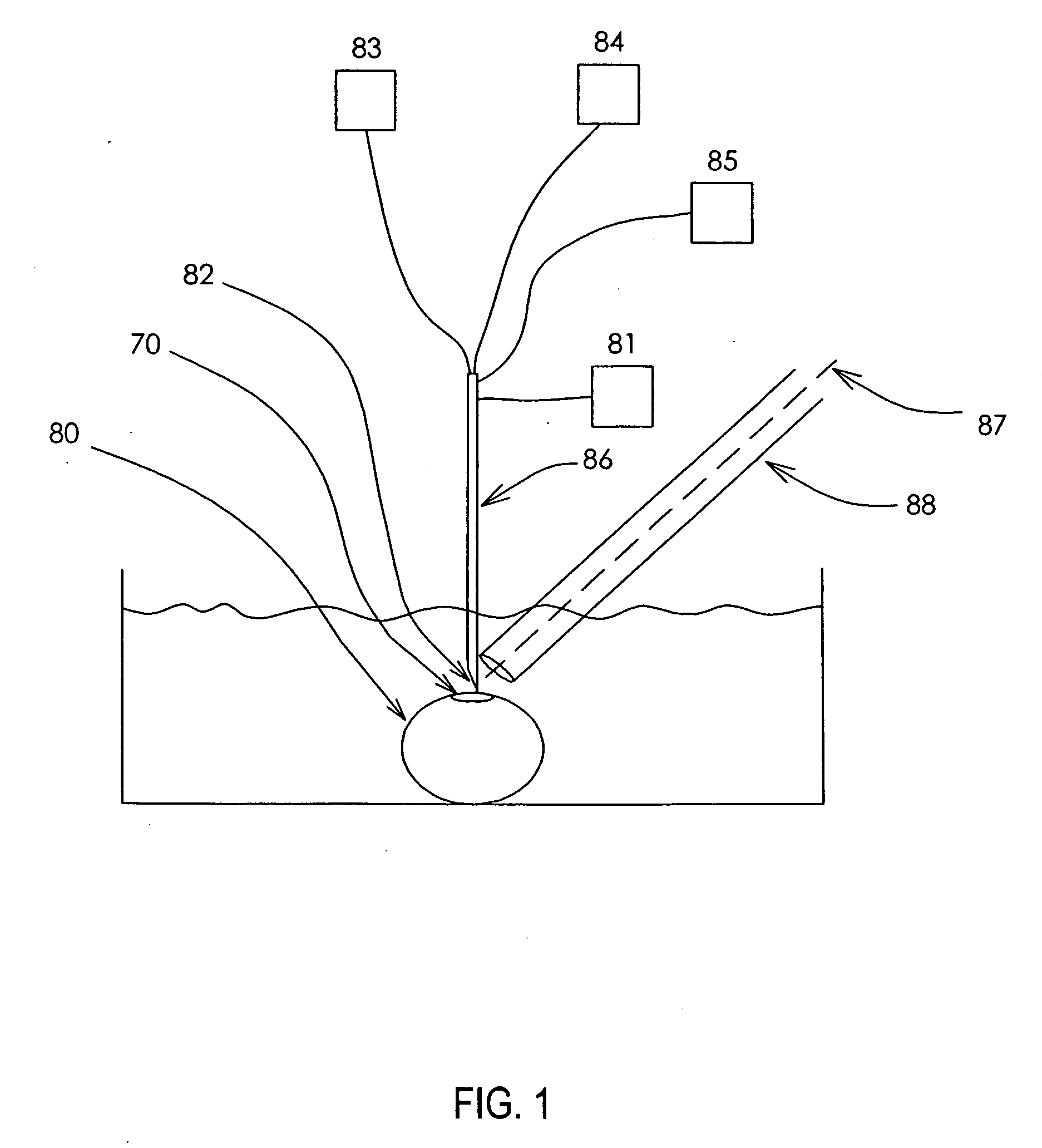
[0013]In one embodiment, the devices of the invention include a laser light source. The laser light source may be used to illuminate the needle, for example, the tip of the needle may be illuminated by the laser light source. In one embodiment, the laser light travels down the needle and illuminates the end of the needle, e.g., the bevel of the needle is illuminated. For example, the laser light source may be connected to the needle by a fiber optic line as seen in FIG. 1. Typically, the devices of the invention include an injector. The injector may be operably attached to the needle so as to facilitate the injection of a substance through the injection needle to an object such as a germinal disc. In one embodiment, the injector can provide for a reduced pressure in the injection needle thereby facilitating the drawing of a substance into the needle. The injector can also provide for a positive pressure which can facilitate the expulsion of a substance from the injection needle.
[0021]In one specific embodiment, the invention comprises an optical microscope, a microinjection system and an oblique macro-monitoring unit for the microinjection of an avian ovum. The assembly or device of the present invention allows the operator to monitor the extent of the microinjection into an avian embryonic cell or cytoplast without interference from the optically opaque egg yolk.

Problems solved by technology

However, the use of retroviruses, poses certain limitations, including limitations to the size of the transgene.
However, to date, the production of transgenic chickens by means of DNA microinjection has been both inefficient and time consuming and has produced inconsistent results and a lack of germ-line transmission of the injected DNA.
The problems associated with transgenic avian production by microinjection are believed to be due, at least in part, to the delicate structure of the fertilized or unfertilized germinal disc and the lack of devices and methods of manipulating the germinal disc.

Method used


Image

  • Microinjection devices and methods of use
  • Microinjection devices and methods of use
  • Microinjection devices and methods of use

Examples


example 1

Production of Transgenic Hens by Microinjection of an Ovomucoid Promoter-Bacterial Artificial Chromosome Expression Vector Transgene

[0123]BAC clones OMC24-IRES-LC and OCM24-IRES-HC were used to produce transgenic chickens by microinjection. A detailed description of these BACs is disclosed in U.S. patent application Ser. No. 11 / 047,184, filed Jan. 31, 2005, the disclosure of which is incorporated in its entirety herein by reference. Briefly, each BAC includes a 70 kb chicken ovomucoid gene region with a coding sequence for either a heavy chain (HC) or light chain (LC) of a particular human IgG1 antibody. The HC and LC sequences are under the translational control of an internal ribosome entry site (IRES) which is inserted in the 5′ UTR of the ovomucoid gene region.

[0124]The BACs were linearized by enzymatic restriction digest. The digested DNA was phenol / CHCl3 extracted, ethanol precipitated, suspended in 0.25 M KCl and diluted to a working concentration of approximately 60 μg / ml (3...

example 2

Production of Antibody by Transgenic Hens

[0129]Transgenic chicks produced as described in Example 1 were grown to maturity. Eggs were collected from the hens and egg white material was assayed for the IgG1 using sandwich ELISA.

[0130]The eggs were cracked and opened and the whole yolk portion was discarded. Both the thick and thin egg white portions were kept. 1 ml of egg white was measured and added to a plastic Stomacher 80 bag. A volume of egg white buffer (5% 1M Tris-HCl pH 9 and 2.4% NaCl) equal to two times the volume of egg white was added to the egg white. The egg white-buffer mixture was paddle homogenized in the Stomacher 80 at normal speed for one minute. The sample was allowed to stand overnight and homogenation was repeated. A 1 ml sample of the mixture was used for testing.

[0131]A Costar flat 96-well plate was coated with 100 ul of C Goat-anti-Human kappa at a concentration of 5 μg / ml in PBS. The plate was incubated at 37° C. for two hours and then washed. 200 μl of 5% ...

example 3

Production of Transchromosomic Chickens Using Satellite DNA-Based Artificial Chromosomes

[0133]Satellite DNA-based artificial chromosomes (ACEs, as described in Lindenbaum et al Nucleic Acids Res (2004) vol 32 no. 21 e172) were isolated by a dual laser high-speed flow cytometer as described previously (de Jong, G, et al. Cytometry 35: 129-133, 1999).

[0134]The flow-sorted chromosomes were pelleted by centrifugation of a 750 μl sample containing approximately 106 chromosomes at 2500×g for 30 min at 4° C. The supernatant, except the bottom 30 microliters (μl) containing the chromosomes, was removed resulting in a concentration of about 7000 to 11,500 chromosomes per μl of injection buffer (Monteith, et al. Methods Mol Biol 240: 227-242, 2004). Depending on the number of chromosomes to be injected, 25-100 nanoliters (nl) of injection buffer was injected per embryo.

[0135]Embryos for this study were collected from 24-36 week-old hens from commercial White Leghorn variety of G. gallus. Embr...


PUM

PropertyMeasurementUnit
angleaaaaaaaaaa
angleaaaaaaaaaa
angleaaaaaaaaaa

Abstract

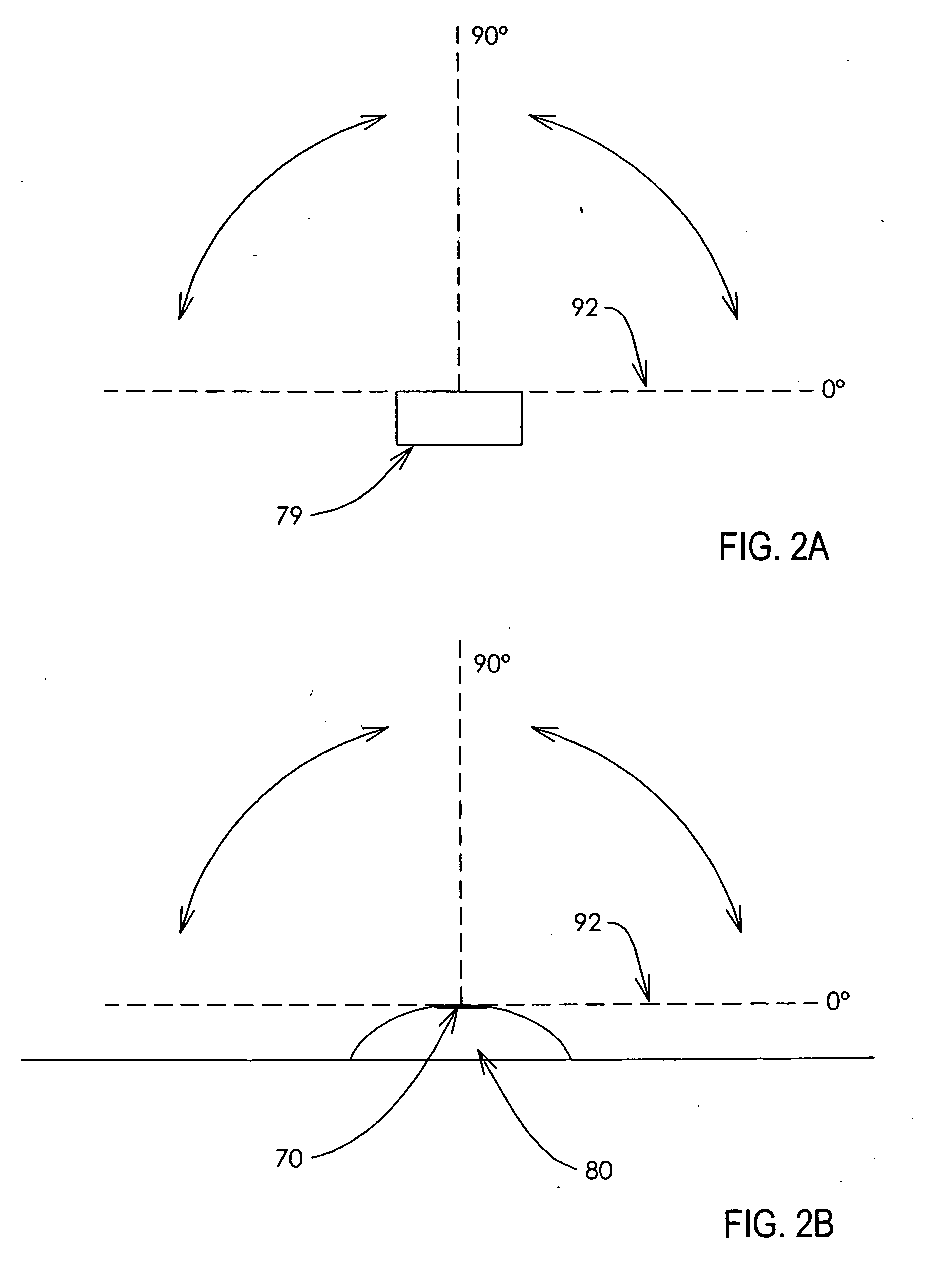
The present invention provides for microinjection devices comprising a needle and a viewing instrument wherein the viewing instrument provides viewing of an object to an operator from an angle other than a right angle to the object.

Description

[0001]This application is a continuation-in-part of U.S. patent application Ser. No. 11 / 159,973, filed Jun. 23, 2005, the disclosure of which is incorporated in its entirety herein, which claims the benefit of U.S. provisional application No. 60 / 652,324, filed Feb. 11, 2005, the disclosure of which is incorporated in its entirety herein, and is a continuation-in-part of U.S. patent application Ser. No. 09 / 919,143, filed Jul. 31, 2001, the disclosure of which is incorporated in its entirety herein, which claims the benefit of U.S. provisional application No. 60 / 269,012, filed Feb. 13, 2001, the disclosure of which is incorporated in its entirety herein.FIELD OF THE INVENTION[0002]The invention provides for microinjection devices which facilitate the precise delivery of a substance to an object. The invention also provides for methods of using the devices.BACKGROUND[0003]The use of transgenic technology to introduce heterologous DNA into animals has been contemplated for the productio...

Claims


Application Information

Patent Timeline
Patent Type & Authority Applications(United States)
IPC IPC(8): C12M1/00A01K67/027A61M31/00A61M37/00
CPCA01K67/0275A01K2217/05G02B21/32C12M35/00A61M37/00
Inventor CHRISTMANN, LEANDRO
Owner SYNAGEVA BIOPHARMA CORP
Learn More