High frequency power supply device and high frequency power supplying method

a high frequency power supply and high frequency technology, applied in the direction of plasma technique, dynamo-electric converter control, coatings, etc., can solve the problems of intermediate extinguishing of plasma after it has been ignited, unfavorable situations, and inability to quickly and stably generate plasma, etc., to achieve high precision, high precision, and high precision

Inactive Publication Date: 2008-06-05
PEARL IND +1
View PDF3 Cites 24 Cited by
  • Summary
  • Abstract
  • Description
  • Claims
  • Application Information

AI Technical Summary

Benefits of technology

[0023]According to the above method, in the first high frequency power supply block, the heterodyne detection signal of the reflected wave is used as a control signal for being fed back to the power amplifier and for impedance matching, and the following processes are performed simultaneously: the servo motor mechanism is used to achieve matching in the impedance match block; prior to the matching by the servo motor mechanism, an electronic mechanism can be used to optimize an oscillating frequency and a high frequency power value instantaneously with a high precision. Furthermore, in the second high frequency power supply block, an electronic mechanism can also be used to optimize both an oscillating frequency and a high frequency power value instantaneously with a

Problems solved by technology

Unfortunately, the following problems are present with respect to the control by means of impedance matching in the approach (2).
Consequently, even if the servo motor mechanism together with the impedance matcher is used to achieve matching, various unfavorable situations may occur due to an insufficient follow-up speed.
That is, due to inertia of the servo motor, etc., there may be a limitation of shortening the adjustment period, i.e., the response time of the impedance matching, which results in the occurrence

Method used


Image

  • High frequency power supply device and high frequency power supplying method
  • High frequency power supply device and high frequency power supplying method
  • High frequency power supply device and high frequency power supplying method

Examples


first embodiment

A First Embodiment

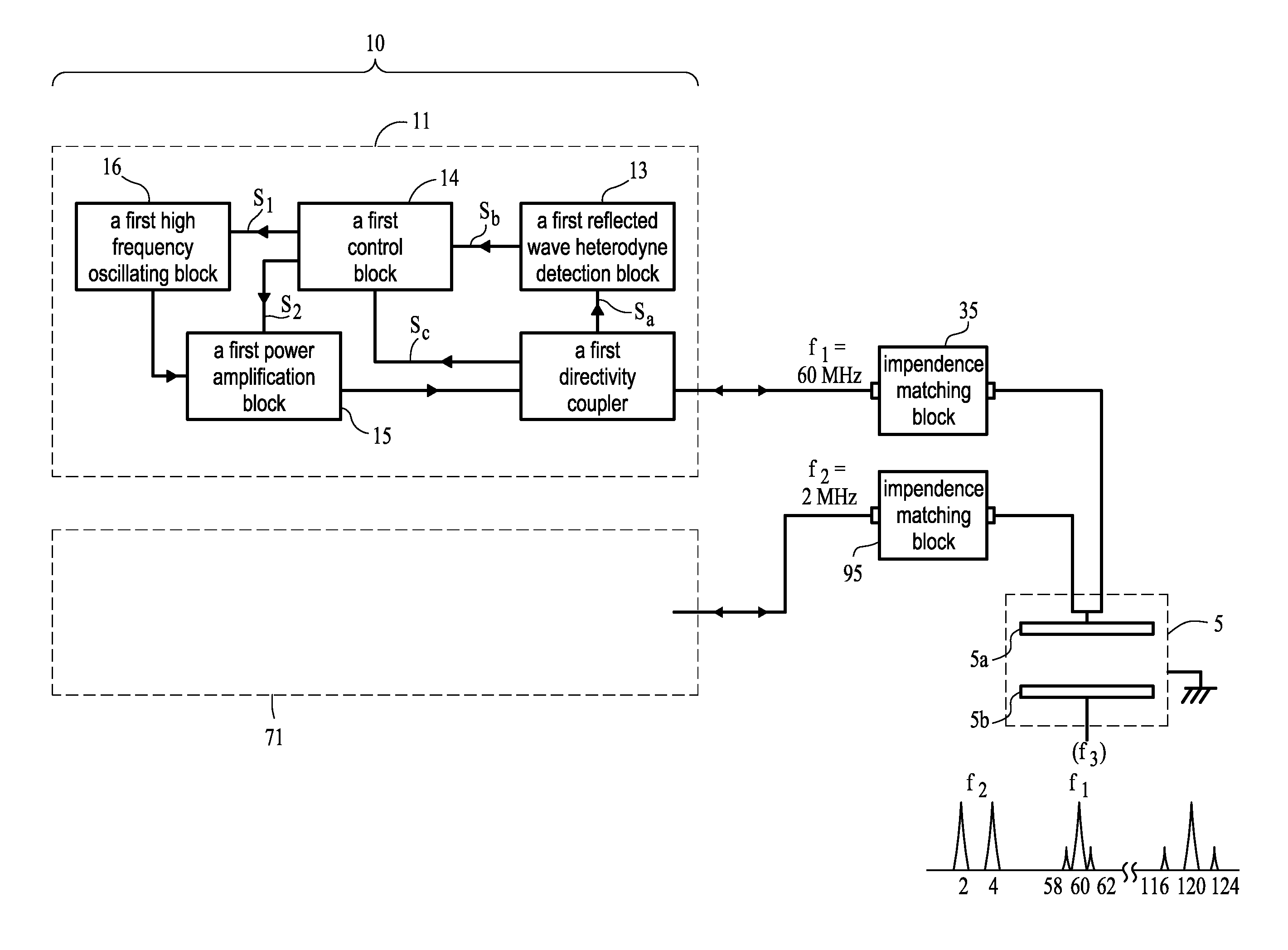
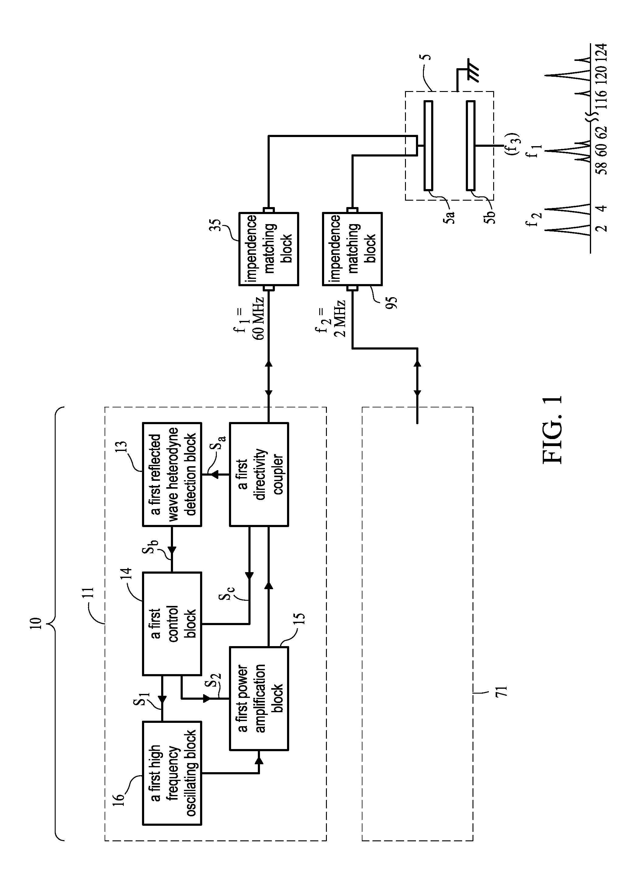
[0037]FIG. 1 is a block diagram depicting a high frequency power supply device 10 according to the first embodiment of the invention. In FIG. 1, high frequency power at a first frequency f1 is supplied from a first high frequency power supply block 11 to a plasma processing chamber 5, and high frequency power at a second frequency f2, lower than the first frequency f1, is supplied from a second high frequency power supply block 71 to the plasma processing chamber 5. In FIG. 1, although the plasma processing chamber 5 is illustrated as a plasma processing chamber provided with parallel flat plates, an electrode plate 5a and an electrode plate 5b, any other apparatus form may be used, provided that it is a processing chamber which is supplied with high frequency power to generate plasmas. Further in FIG. 1, although a substrate to be plasma-processed (e.g., a semiconductor wafer) is mounted on the electrode plate 5b, it also can be mounted on the electrode plate 5a. ...

second embodiment

A Second Embodiment

[0050]FIG. 5 is a block diagram depicting a second high frequency power supply block 71 used in a high frequency power supply device according to the second embodiment of the invention. In a first high frequency power supply block supplying high frequency for generation of plasmas, the same device is used as in the first embodiment. In the first embodiment, any high frequency power supply is possible provided that the high frequency power supply block 71 for controlling ions can supply high frequency power at a frequency below the first frequency. However this embodiment is characterized in that there is provided a control board (a second control block) 74, which controls an oscillating frequency of an oscillating block (a second high frequency oscillating block) 76 of the high frequency power supply block for controlling ions and an output of a power amplifier (a second power amplification block) 75, and which inputs a frequency control signal K1 and an output co...

examples

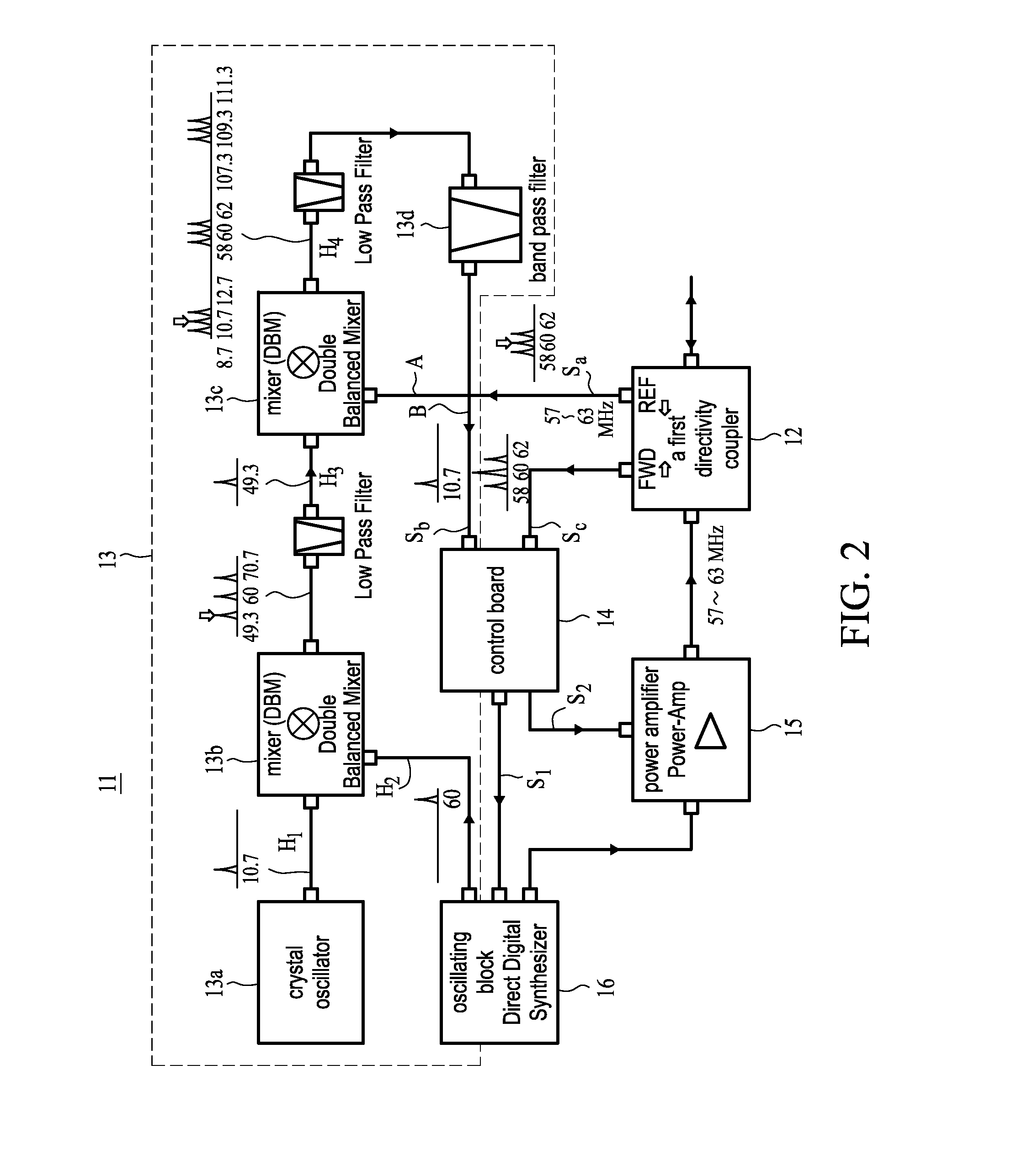
[0056]Hereinafter, there will be depicted a result obtained from measuring a frequency spectrum of a reflected wave signal at a point A (a signal Sa) and a point B (a signal Sb) of the first high frequency power supply block (see FIG. 1 and FIG. 2) by using the first high frequency power supply block 11 as illustrated in FIG. 2, and the second high frequency power supply block 71 as illustrated in FIG. 3. FIG. 8 is a diagram depicting a frequency spectrum of a reflected wave signal when NF3 is used in a plasma gas at a pressure of 150 mTorr with traveling wave power of 1 kW. Reflected wave power is 20 W at the point A prior to heterodyne detection. At this time, a primary peak of the reflected wave is at 61.4 MHz and has a magnitude higher than those of side peaks deviating by approximately 2 MHz, but is difficult to be separated from the side peaks and thus taken in. In the prior art, the reflected wave signal in this status was applied to a feedback in power amplification, and the...


PUM

PropertyMeasurementUnit
Frequencyaaaaaaaaaa
Electric impedanceaaaaaaaaaa

Abstract

A high frequency power supply device and power supplying method are disclosed, which can rapidly and accurately control power used for generation of plasmas. The device includes a first high frequency power supply, providing power at frequency f1, and a second high frequency power supply providing power at frequency f2 (f1>f2). The first power supply includes: a first high frequency oscillator, which excites the high frequency power at the first frequency and has a variable frequency; a first power amplification block, which amplifies the power of the high frequency oscillator; a heterodyne detection block, which performs heterodyne detection of a reflected wave; and a first control block, which receives a signal after detection of the heterodyne detection block and a traveling wave signal, and controls an oscillating frequency of the first high frequency oscillating block and an output of the first power amplification block.

Description

FIELD OF THE INVENTION [0001]The present invention relates to a high frequency power supply device and a high frequency power supplying method and, in particular, to a high frequency power supply device and a high frequency power supplying method for processing plasmas used in semiconductor device fabrication and the like.BACKGROUND [0002]A semiconductor device, such as DRAM, SRAM, Flash Memory, Optical Semiconductor Chip, etc., is fabricated through processes of forming a semiconductor layered film on a semiconductor substrate, perforating respective portions through etching, and filling with a metal film etc., so as to realize electrical connections, and further through processes of disposing trenches surrounding prescribed regions and filling with an oxide film so as to realize insulation. In the process of etching the layered film to form holes or trenches, various etching methods can be used, but plasma processing can be used to achieve deep and steep etching with a high aspect...

Claims


Application Information

Patent Timeline
IPC IPC(8): C23F1/08B05C11/00H02M5/02
CPCH01J37/32091H05H1/46H01J37/32174H01J37/32165H01L21/3065H02M3/28H05B7/00H05H7/02H05H1/4645
Inventor HAYANO, EIICHNAKAMURA, TAKESHIMAEKAWA, YASUNORIIIZUKA, HIROSHICHEN, JINYUAN
Owner PEARL IND
Why Eureka
Try Eureka