Convective earrh coil

Inactive Publication Date: 2008-06-05
CLARK STEVEN JOSEPH
View PDF8 Cites 21 Cited by
  • Summary
  • Abstract
  • Description
  • Claims
  • Application Information

AI Technical Summary

Benefits of technology

[0036]Advantageously, the said means for inducing flow of said ground water may also promote the natural stratification of the ground water into thermal layers, allowing for storage of thermal energy. Preferably said system for heat rejection and extraction between a heat transfer fluid or gas and the earth water cooling means is connec

Problems solved by technology

While the value of these systems in the savings of heating and cooling energy has been profound, the real world-building owners generally have not been able to justify the cost, complexity or size of the ground coil in the competitive environment they face.
For example, most large commercial buildings and schools use vertical loops because the land area required for horizontal loops would be prohibitive.
Installation costs depend on geological conditions and local drilling industry experience.
Both horizontal and vertical closed loop ground coil systems can be relatively expensive compared with above ground air based systems due to the extensive size requirements.
This large area is the result of the low thermal heat transfer rate of conduction from the pipe to the ground and by poor conduction through the ground.
Unfortunately, over time, the exposed pipe coils become fouled with dirt and microbiological growth and lose their effectiveness.
Open loop systems do have some associated challenges: (1) Local ground water chemical conditions can lead to fouling the heat pump's heat exchanger particularly if oxygen, carbon dioxi

Method used


Image

  • Convective earrh coil
  • Convective earrh coil
  • Convective earrh coil

Examples


Embodiment Construction

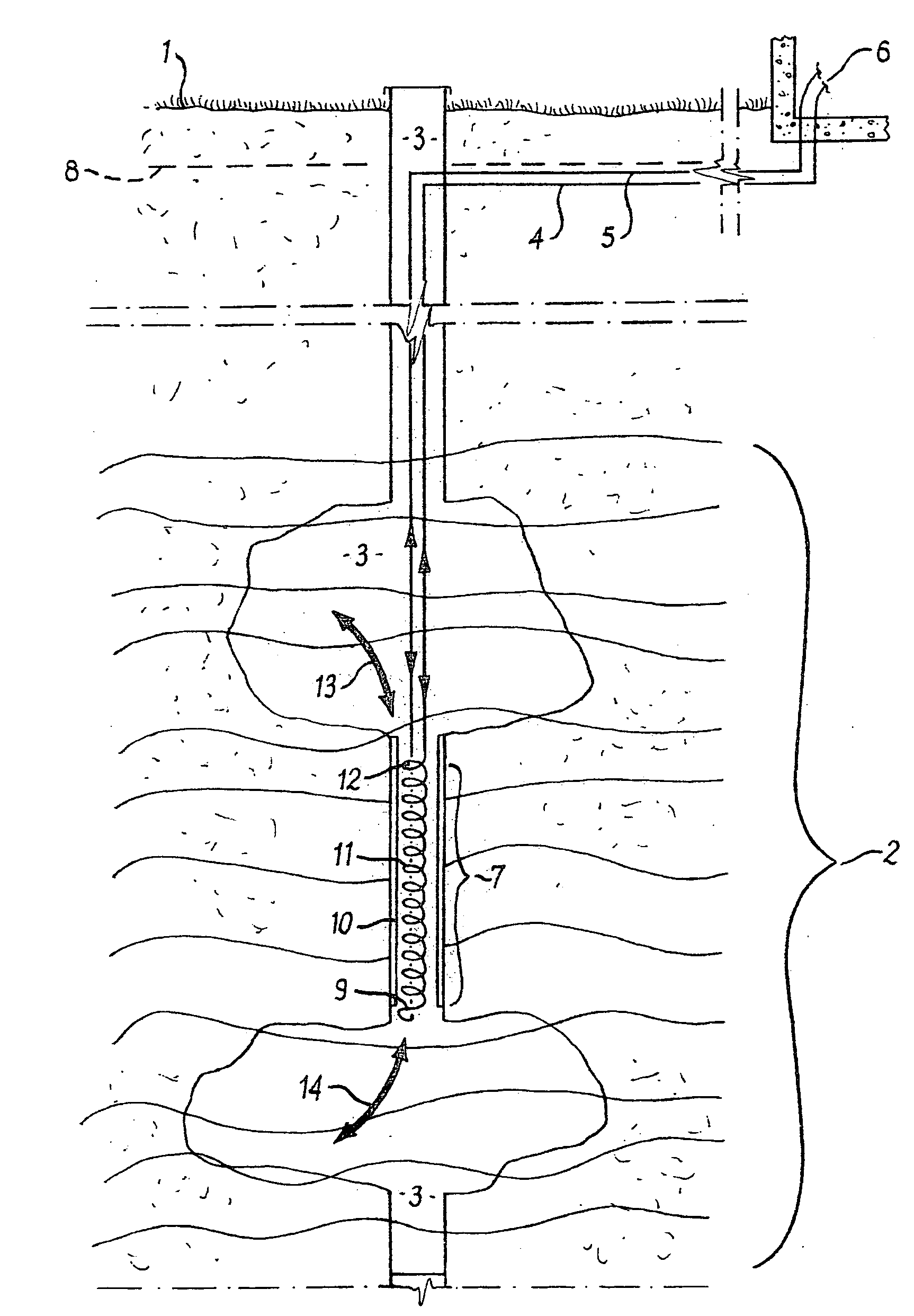
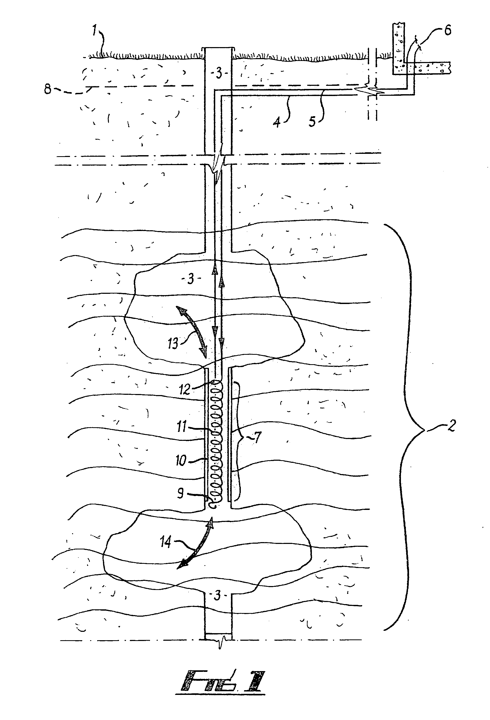
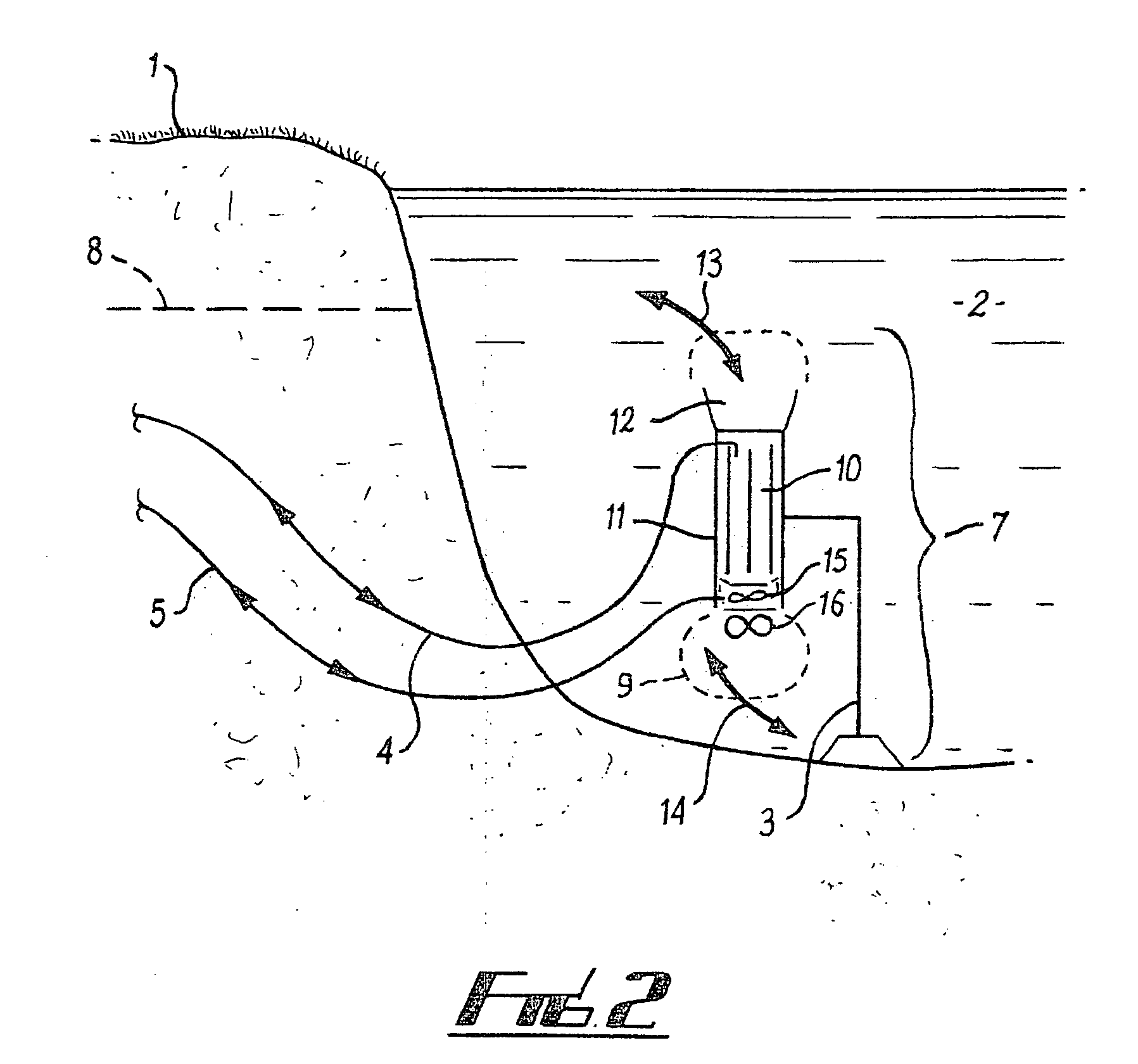
[0040]Referring to FIG. 1, a portion of an aquifer some depths below the earth surface 1 is generally shown by reference numeral 2. A well 3 is drilled from the earth surface 1 until it reaches the desired aquifer 2. Pipes 4 and 5 for supplying and returning the heat transfer fluid from the thermal load 6 to the convective earth coil 7 are run below the earth's surface 1 (preferably below the frost line 8) to the well 3, and down the well 3 to the convective earth coil 7. In FIG. 1, the convective earth coil 7 is generally comprised of inlet 9, a vertical chamber 10, a convective heat exchanger 11, and a discharge outlet 12. In FIG. 1 the convective heat exchanger 11 is represented as a spiral tube within a tube.

[0041]The convective earth coil can be used to inject heat into the ground or extract heat energy from the ground. In the illustrated embodiment, in operation in the heat injection mode, warm heat transfer fluid flows from the thermal load 6 through pipe 4 into the top porti...


PUM


Abstract

The present invention relates to a method of heat rejection and extraction between a fluid and the earth, providing for a high efficiency convective heat exchanger located in ground water, a means for inducing flow of said ground water at its initial temperature from ground water pool through said heat exchanger, a means of inducing heat transfer from said ground water to said heat transfer fluid or gas, a means of discharging said ground water at a new temperature back into said ground water pool, and a piping system suitable to transport said heat transfer fluid from a thermal load at some remote location at a first temperature, though the said convective heat exchanger and transporting the heat transfer fluid at a new temperature to the location(s) where the thermal energy is utilized.

Description

TECHNICAL FIELD OF THE INVENTION[0001]The present invention relates to a method of heat rejection and extraction between a fluid and the earth.BACKGROUND OF THE INVENTION[0002]Traditionally, if the designer of a heating and / or cooling system for building wanted to substantially improve the energy efficiency of his building, he could invest in the installation of a ground-source (or earth-coupled) heat-pump system. This would require the installation of one or more water-source heat-pumps in the building and installing a dedicated piping system from the water-source heat-pumps to a ground coil. The ground coil heating and cooling systems use the earth as an energy source and heat sink. A series of pipes, commonly called a “loop,” are used to connect the heat pump system to the earth. In a few installations, refrigerant from the heat pump is circulated through the ground in a closed loop. However, the more common loops discussed here use only water or a water and antifreeze mixture. W...

Claims


Application Information

Patent Timeline
IPC IPC(8): F24J3/08
CPCY02E10/12F24J3/081F24T10/10F24T10/40Y02E10/10
Inventor CLARK, STEVEN JOSEPH
Owner CLARK STEVEN JOSEPH
Why Eureka
Try Eureka