Method of fabricating imprint lithography template

a template and imprint technology, applied in the field of template manufacturing, can solve the problems of line width distortion, high price tag, and limited use of uv-nil technology and hot imprint lithography to fabricate templates, and achieve the effect of improving the stability and hardness of hsq film

Inactive Publication Date: 2008-06-05
NATIONAL TSING HUA UNIVERSITY
View PDF2 Cites 35 Cited by
  • Summary
  • Abstract
  • Description
  • Claims
  • Application Information

AI Technical Summary

Benefits of technology

[0013]To achieve the above purposes, we find novel method to convert cage-like HSQ into quartz-like HSQ to improve the stability and hardness of HSQ film. The present invention is a method of fabricating an imprint lithography term plate, where a substrate coated with a transparent conductive layer is cleaned with a chemical solution; then a low-k material is spin-on coa

Problems solved by technology

As conventional projection lithography reaches its limits, next generation lithography (NGL) tools may provide means to further shrink patterns; but it is expected to have a price tag that is prohibitive for many companies.
Nevertheless, the UV-NIL technology and the hot imprint lithography are both limited to fabricating templates; and the line width and quality of the template decide the quality of the imprint result.
In addition, the photo resist having a structure of a high aspect ratio may be collapsed with imperfection on etching and so distortion of the line width oc

Method used


Image

  • Method of fabricating imprint lithography template
  • Method of fabricating imprint lithography template
  • Method of fabricating imprint lithography template

Examples


Embodiment Construction

[0018]The following description of the preferred embodiment is provided to understand the features and the structures of the present invention.

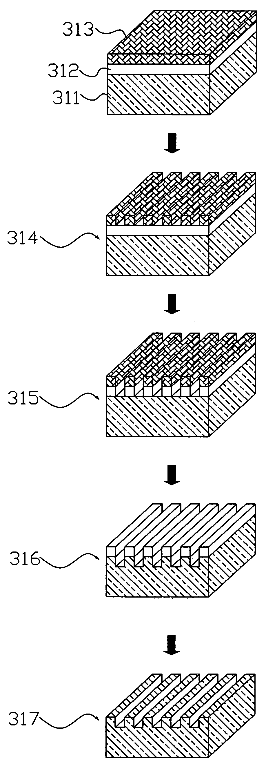
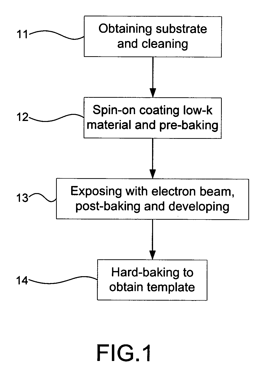
[0019]Please refer to FIG. 1 which is a flow view showing a preferred embodiment according to the present invention. As shown in the figure, the present invention is a method of fabricating an imprint lithography term plate, comprising the following steps:

[0020](a) Substrate obtaining and cleaning 11: A substrate coated with a transparent electrode is obtained to be cIeaned with a chemical solution, where the substrate is made of glass or quartz; and the transparent electrode is made of indium tin oxide (ITO), indium zinc oxide (IZO), indium gallium zinc oxide (IGZO) or zinc oxide (ZnO).

[0021](b) Low-K material spin-on coating and pre-ba king 12: The substrate is spin-on coated with a low-k material to be pre-baked, where the low-k material is a spin-on glass (SOG), hydrogen silsesquioxane (HSQ), methylsilsesquioxane (MSQ), organosilicate gla...


PUM


Abstract

A template, stamp or mold is fabricated by using a low-k material. The structure of the low-k material is transformed when it is baked in a novel heating process. Thus, the template is fabricated to obtain a high hardness and a high aspect-ratio with a low dose of electron beam lithography and an optimized baking process. Consequently, the residual; layer at photoresist bottom is reduced and the time for reactive ion etching is saved. In the end, the stability and the integrity is improved. Hence, the present invention is a solution for fabricating a template, stamp or mold with the feature size from sub-micrometer down to nanometer level.

Description

FIELD OF THE INVENTION[0001]The present invention relates to fabricating a template; more particularly, relates to obtaining a template for a UV-imprinting lithography and a micro-contact printing.DESCRIPTION OF THE RELATED ARTS[0002]According to the ITRS (International Technology Road map for Semiconductors Conference) 2005 update, the 45 nm gene ration will become standard in 2010. As design rules of ULSI continue to shrink, interconnect processes must be compatible with device road maps and meet manufacturing targets. As conventional projection lithography reaches its limits, next generation lithography (NGL) tools may provide means to further shrink patterns; but it is expected to have a price tag that is prohibitive for many companies. The development of both light source and optics to support the sources are primarily responsible for cost rising of NGL tool.[0003]In 1995, Stephen Y. Chou, etc. revealed an imprint lithography technology (Stephen Y. Chou, Peter R. Krauss, and Pr...

Claims


Application Information

Patent Timeline
IPC IPC(8): G03C5/00
CPCB82Y10/00G03F7/0017G03F7/0002B82Y40/00
Inventor LIAO, CHEN-LIANGCHEN, JIANN-HENGHUANG, FON-SHAN
Owner NATIONAL TSING HUA UNIVERSITY
Why Eureka
Try Eureka