Tubular Polymer Stent Coverings

Inactive Publication Date: 2008-06-05
UNIV OF FLORIDA RES FOUNDATION INC
View PDF22 Cites 79 Cited by
  • Summary
  • Abstract
  • Description
  • Claims
  • Application Information

AI Technical Summary

Benefits of technology

[0014]Appropriate modeling of covered stents will assist in designing suitable coverings, and help to reduce the failure rate of covered microstents. The present inventors have used the finite element method to determine the mechanical properties of the covered microstent and investigate the effects of the covering on the mechanical behavior of the covered microstent. Variations in the mechanical properties of the covered microstent such as deployment pressure, elastic recoil and longitudinal shortening due to change in thickness and material properties of the cover

Problems solved by technology

The voids between the various support elements of the stent can be problematic.
For example, lumen wall tissue directly adjacent to such voids is not supported and can prolapse.
Similarly, plaque or other material not directly supported by a stent element could also prolapse or come loose and be swept downstream to cause an embolism.
Another problem encountered with conventional stent configurations is the risk of over-expanding the stent so as to unnecessarily traumatize or otherwise distort the body lumen at the deployment site.
While a particular stent configuration may inherently limit the maximum diameter that can be achieved, such stents can nonetheless exceed the maximum diameter that can be tolerated by the body lumen at the deployment site.
Unfortunately, previous attempts at covering stents have caused undesirable changes

Method used


Image

  • Tubular Polymer Stent Coverings
  • Tubular Polymer Stent Coverings
  • Tubular Polymer Stent Coverings

Examples


example 1

Evaluation of Materials for Stent Coverings

[0058]Tear-resistant, biocompatible elastomeric polymer materials will be chosen for making tubes. Two types of commercially available solution grade (SG) thermoplastic materials will be selected: a polyurethane (TECOFLEX SG-80A, THERMEDICS Polymer Products, Woburn, Mass.) and a few silicone-polyurethane copolymers (CARBOSIL 40 90A, PURSILI 20 80A and PURSIL AL5 75A, The POLYMER TECHNOLOGY GROUP Inc., Berkeley, Calif.). TECOFLEX SG-80A is an aliphatic polyether based thermoplastic polyurethane (TPU). PURSIL silicone-polyether-urethane and CARBOSIL silicone-polycarbonate-urethane are thermoplastic copolymers containing silicone in the soft segment. PURSIL 20 80A is an aromatic silicone polyetherurethane whereas PURSIL AL5 75A is an aliphatic silicone polyetherurethane. Table 1 lists some of the physical test data of these materials reported by the manufacturers. From the table it is clear that these materials cover a range of mechanical prop...

example 2

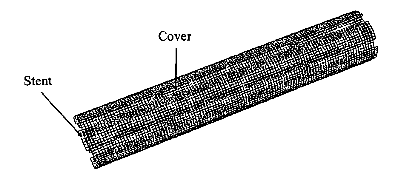
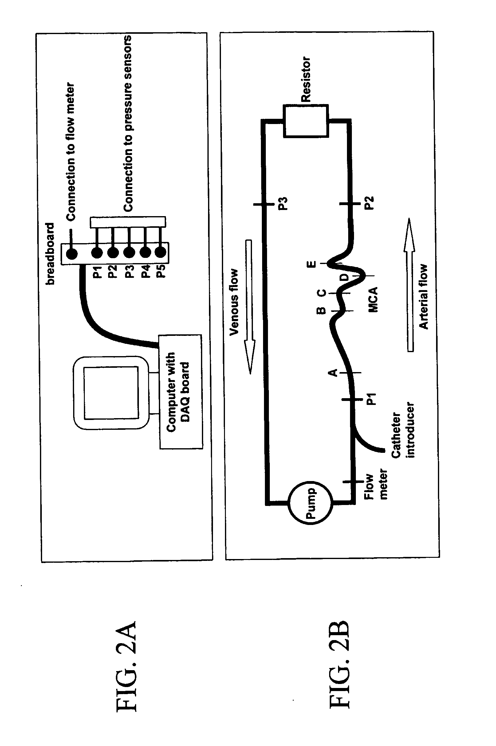
In Vitro Performance Testing of Covered Stent

[0061]Tests will be performed to evaluate the robustness of the device fabrication and to determine the device performance in vitro under various conditions.

[0062]A. Mechanical Testing of the Covered Stent by INSTRON

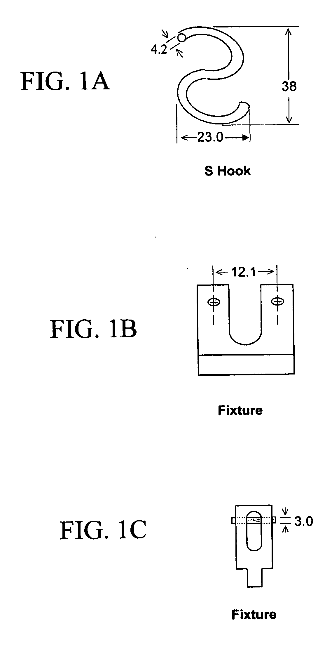
[0063]Flexibility and maneuverability testing is useful to predict the feasibility of navigating the device through the tortuous intracranial vasculature system in the brain before the final deployment. A three-point bend test on the double lumen tubular micrograft with uncured adhesive will be performed. FIGS. 1A-1C show an “S” hook (FIG. 1A) and three-point bend fixture (FIGS. 1B and 1C). The bend test fixture and an “S” hook for the bend test will be made in the machine shop.

[0064]Mechanical testing on the deployed covered stent will be performed using an INSTRON model 4301 (INSTRON Corporation, Canton, Mass.). Compression and three-point bend tests will be performed. The compression test will evaluate how much radial press...

example 3

In Vivo Testing of Covered Stent in Rabbit Arteriovenous Fistula (AVF) Model

[0074]Under protocols approved by University of Florida's Institutional Animal Care and Use Committee, covered stents of the invention were tested for efficacy and histological compatibility in New Zealand White (NZW) rabbits.

[0075]Histological analysis of the effect of device placement was conducted in the normal common carotid artery. A vascular sheath was placed in the femoral artery of a NZW rabbit. Using endovascular techniques, a microstent covered with tubular polymer was navigated through the vasculature towards the common carotid artery. The device was deployed within the vessel and angiography was performed to confirm patency. Following device placement, the animal was monitored for a period of two to six weeks, depending on the experimental group to which it was assigned. At the end of the determined monitoring period, angiography of the stented vessel was performed to reveal angiographic patency....


PUM


Abstract

The present invention concerns thin, flexible tubings useful as stent coverings; covered stents; methods for applying such coverings to stents; and methods for reinforcing biological lumens, such as the intracranial vasculature, by introducing the covered stent into the biological lumen and positioning the covered stent at a target site, such as the site of a vascular defect.

Description

CROSS-REFERENCE TO RELATED APPLICATION[0001]The present application claims benefit of U.S. Provisional Application Ser. No. 60 / 586,552, filed Jul. 9, 2004, which is hereby incorporated by reference herein in its entirety, including any figures, tables, nucleic acid sequences, amino acid sequences, and drawings.BACKGROUND OF THE INVENTION[0002]The present invention generally relates to intravascular stents and more particularly pertains to covers that envelop the stent's supporting structure.[0003]Stents or expandable grafts are implanted in a variety of body lumens in an effort to maintain patency and / or to treat disease. These devices are typically intraluminally implanted by use of a catheter which is inserted at an easily accessible location and then advanced through the vasculature, for example, to the deployment site. The stent is initially maintained in a radially compressed or collapsed state to facilitate maneuvering within the body lumen. Once in position, the stent is depl...

Claims


Application Information

Patent Timeline
IPC IPC(8): A61F2/82A61F2/06
CPCA61F2/06A61F2/07A61F2002/072A61F2002/075A61F2250/0067A61F2/90A61F2210/0061
Inventor MERICLE, ROBERT A.SANTRA, SWADESHMUKULBATICH, CHRISTOPHE D.BURRY, MATTHEW V.WATKINS, COURTNEY S.
Owner UNIV OF FLORIDA RES FOUNDATION INC
Why Eureka
Try Eureka