Charged Beam Gun

a charge beam and beam gun technology, applied in the direction of material analysis using wave/particle radiation, instruments, nuclear engineering, etc., can solve the problems of increasing leakage current into an insulating area, reducing dielectric strength, and preventing the downsizing of the body of the charge beam gun, so as to prevent an increase in leakage current and improve the dielectric strength. , the effect of high reliability

Inactive Publication Date: 2008-06-12
HITACHI HIGH-TECH CORP
View PDF4 Cites 9 Cited by
  • Summary
  • Abstract
  • Description
  • Claims
  • Application Information

AI Technical Summary

Benefits of technology

[0010]The above configuration can suppress an increase in leakage current resulting from condensation on or moisture absorption into the surface of an insulating material in the vicinity of a high-voltage connection of a charged beam gun in an ultra-high vacuum container, thereby improve dielectric strength, and thus achieve a size-reducible, highly reliable charged beam gun. Moreover, this configuration enables the charging of the insulating liquid into the connection space and the discharge, recovery and reuse of the insulating liquid from the connection space wit...

Problems solved by technology

The above related art method in which a gap is provided in the vicinity of the high-voltage connection to increase the creepage distance requires a size of the gap and a creepage distance that are sufficient to keep predetermined dielectric strength, resulting in an obstacle to downsizing the body of the charged beam gun.
Further, changes in the charged beam gun's surrounding environment can possibly cause condensation on or ...

Method used


Image

  • Charged Beam Gun
  • Charged Beam Gun
  • Charged Beam Gun

Examples


Embodiment Construction

[0016]An embodiment of the present invention will be described below with reference to the drawings.

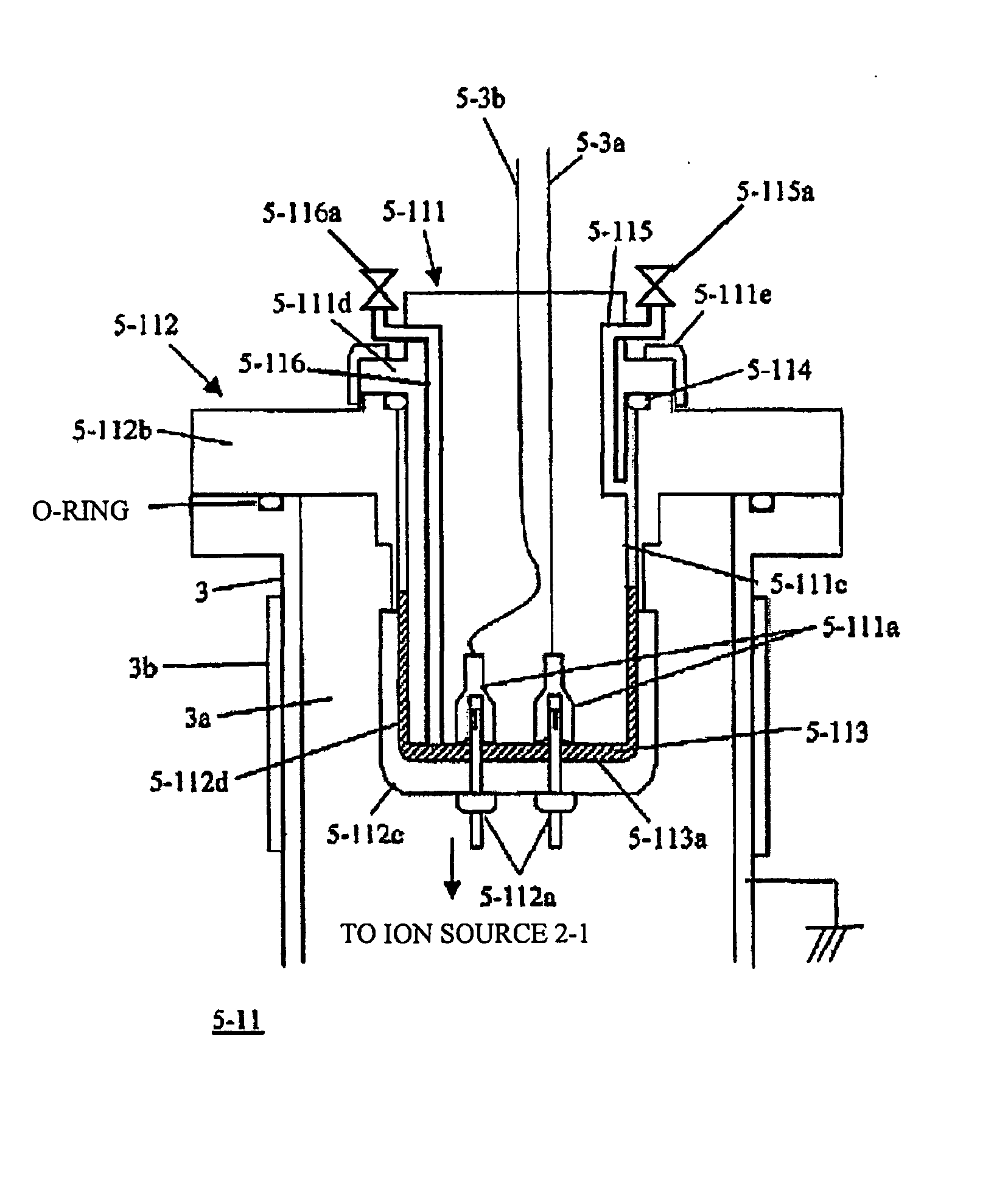
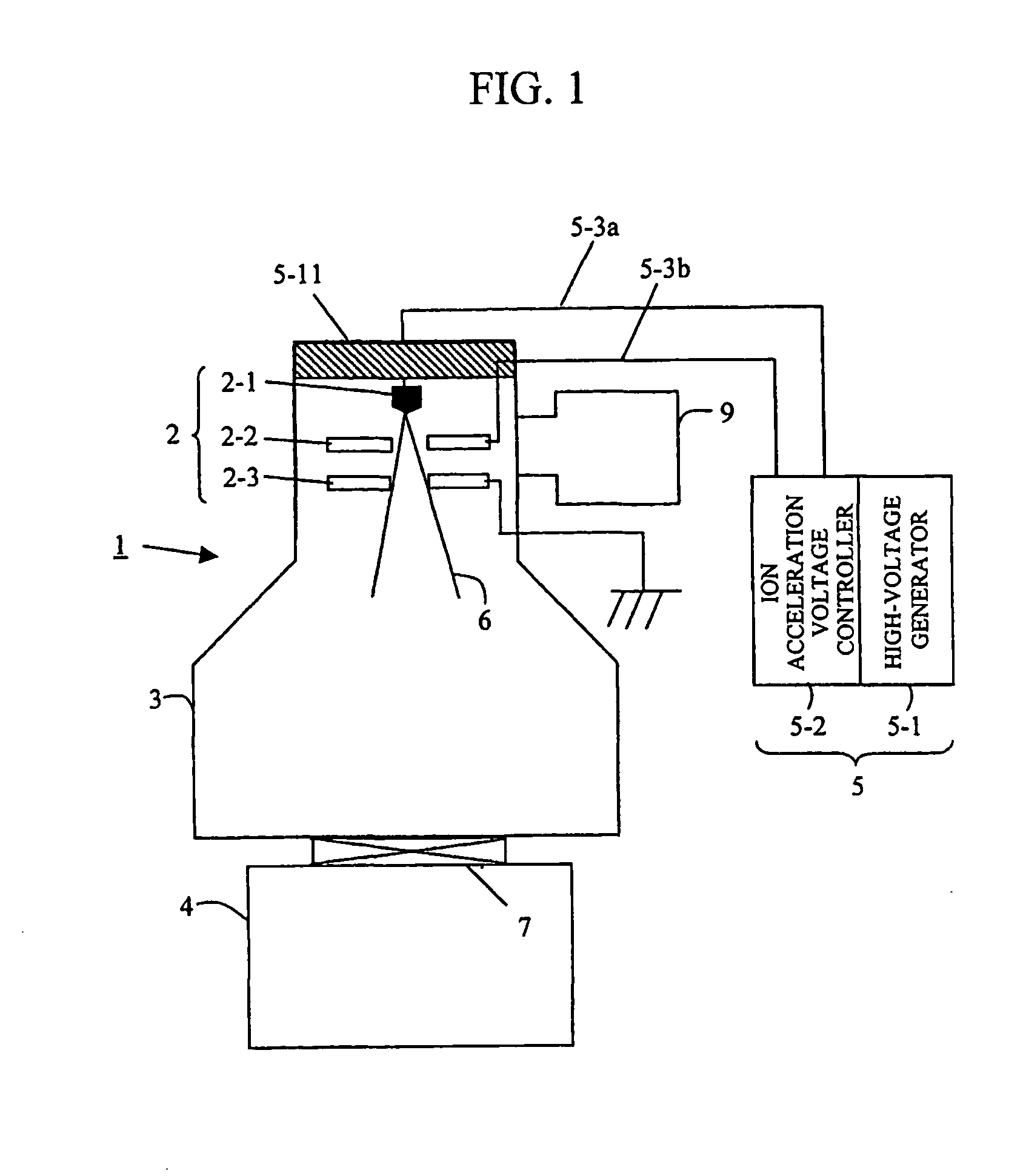
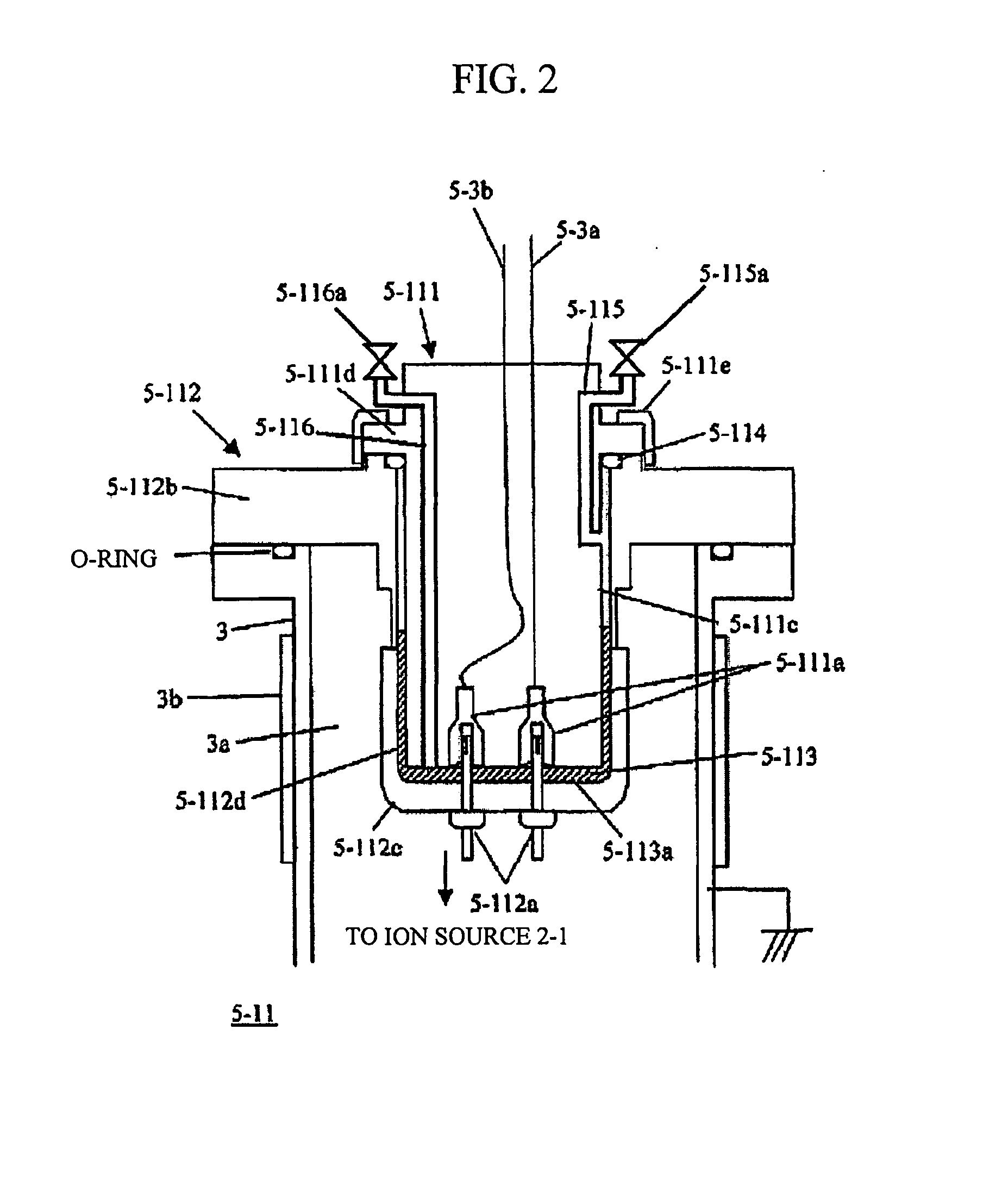
[0017]FIG. 1 is a schematic view of the configuration of an ion beam apparatus according to one embodiment of a charged beam gun of the present invention. An ion beam apparatus1 according to the embodiment includes an ion gun 2, a vacuum container 3, a vacuum pumping system 4, and a high-voltage power supply unit 5. A gate valve 7 is interposed between the vacuum container 3 and the vacuum pumping system 4. The ion gun 2 includes an ion source 2-1, an extraction electrode 2-2, and an acceleration electrode 2-3. The ion gun 2 contained within the vacuum container 3 is evacuated by an ion pump 9. Moreover, the high-voltage power supply unit 5 includes a high-voltage generator 5-1 for ion acceleration and an ion acceleration controller 5-2, and the high-voltage power supply unit 5 applies a high positive voltage to the ion source 2-1 via a high-voltage cable 5-3a and applies a high posit...


PUM


Abstract

The present invention provides a highly reliable charged beam gun designed in consideration for environmental protection, which prevents faulty insulation in a high-voltage connection. An insulating liquid is present in a gap formed between a connecting bushing and a receiving-side flange placed in a vacuum container, and the connecting bushing includes first piping and valve that provide communication between the gap and atmospheric air, and second piping and valve that provide communication between the gap and the atmospheric air, whereby the gap is cut off from the atmospheric air.

Description

CLAIM OF PRIORITY[0001]The present application claims priority from Japanese application JP 2006-334370 filed on Dec. 12, 2006, the content of which is hereby incorporated by reference into this application.BACKGROUND OF THE INVENTION[0002]1. Field of the Invention[0003]The present invention relates to a charged beam gun where a high positive voltage is applied in order to accelerate charged particles, such as a field emission type electron gun of a scanning electron microscope system.[0004]2. Description of the Related Art[0005]For a charged beam gun for an apparatus of which a high ultimate vacuum and a good-quality vacuum are required, such as an electron beam apparatus and an ion beam apparatus, vacuum degassing (or baking) of the charged beam gun is performed in order to achieve a high-level and good-quality vacuum in the body thereof. Here, having regard to thermal resistance of the charged beam gun, maintenance of the charged beam gun, and so on, a high-voltage cable unit and...

Claims


Application Information

Patent Timeline
IPC IPC(8): G01N23/00
CPCG01N23/2251H01J37/065H01J2237/06341H01J2237/006H01J2237/038H01J37/073
Inventor TANAKA, TAKESHIKAGA, HIROYASU
Owner HITACHI HIGH-TECH CORP
Why Eureka
Try Eureka