Composite Resonance Circuit and Oscillation Circuit Using the Circuit

Inactive Publication Date: 2008-06-12
HIRAMA KOICHI
View PDF1 Cites 21 Cited by
  • Summary
  • Abstract
  • Description
  • Claims
  • Application Information

AI Technical Summary

Benefits of technology

[0015]The complex resonance circuit of the present invention has a property that an antiresonance frequency thereof can be adjusted by independently changing voltages or currents for exciting vibrations of the resonance elements. An oscillation circuit and a filter utilizing the property of the complex resonance circuit are configured can be operated on the basis of a new frequency controlling method which has not been conventionally known. The present invention opens the way for realizing a frequency controlling method around at an antiresonance frequency and configuring an oscillation circuit utilizing the frequency controlling method. The frequency controlling method has not been turned into actual utilization since a high impedance is accompanied.
[0016]A piezoelectric device has a plurality of electrodes which are formed on a piezoelectric substrate such as a quartz substrate known as a MCF (Monolithic Crystal Filter). By disposing and connecting the plurality of electrodes so that a plurality of natural vibration modes are generated, an antiresonance frequency appears between resonance frequencies. The dispos

Problems solved by technology

Therefore, there is no other choice to product an oscillation circuit by

Method used


Image

  • Composite Resonance Circuit and Oscillation Circuit Using the Circuit
  • Composite Resonance Circuit and Oscillation Circuit Using the Circuit
  • Composite Resonance Circuit and Oscillation Circuit Using the Circuit

Examples


first embodiment

[0084]the complex resonance circuit according to the present invention, in which the piezoelectric substrate formed from a piezoelectric material (quartz substrate) is utilized, is also referred to as a “complex resonator”. A principle of the present invention, which will be described in reference to the following drawings, is not limited to the embodiments. The complex resonance circuit according to the present invention includes a complex resonance circuit having other piezoelectric materials such as a ceramic. The complex resonance circuit may be configured by at least one strip line element.

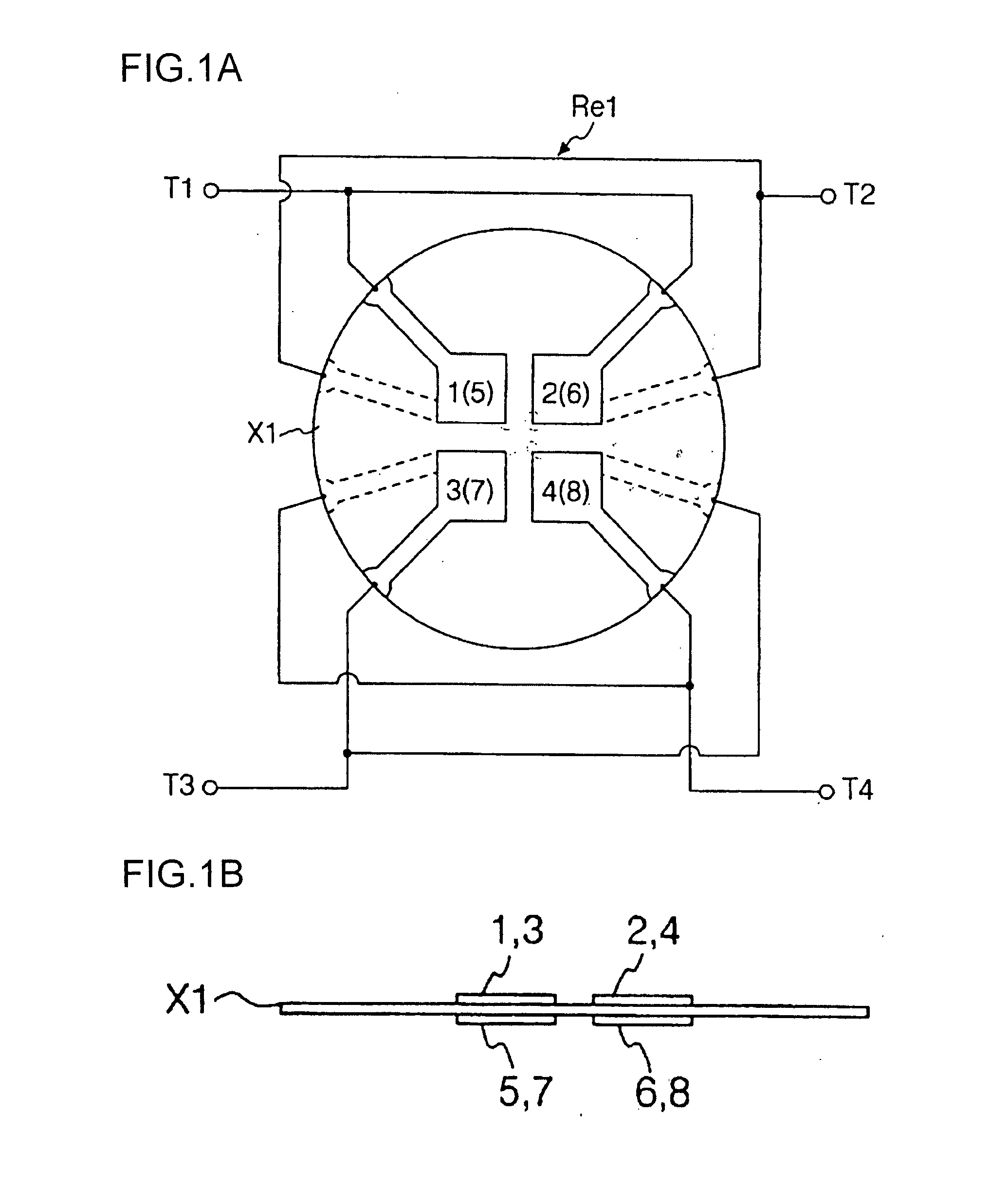
[0085]As shown in FIGS. 1A and 1B, a complex resonator Re1 includes, a first electrode 1, a second electrode 2, a third electrode 3, and a fourth electrode 4 adjacently formed on a front surface of the disciform quartz piezoelectric substrate X1. The first electrode 1, the second electrode 2, the third electrode 3, and the fourth electrode 4 face to each other. The complex resonator Re1 furth...

second embodiment

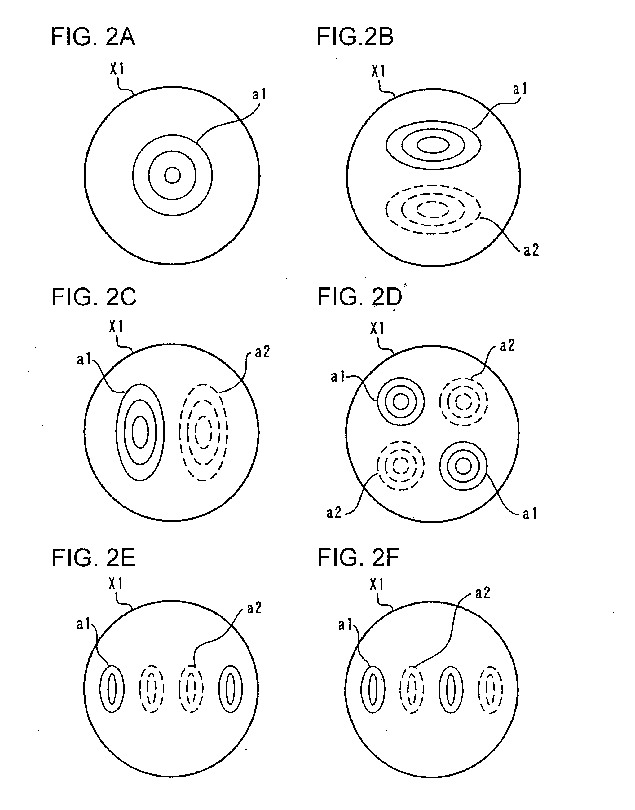
[0157]A first variation of second embodiment will now be described with reference to FIG. 11B. In an electrode structure shown in FIG. 11B, an interdigital electrode pair of 31 and 33 and an interdigital electrode pair of 35 and 37 are serially disposed. Natural vibration modes excited by an AC current supplied across external terminals T23 and T24 are as shown in FIGS. 2E and 2F.

[0158]According to the first variation of second embodiment utilizing the natural vibration modes shown in FIGS. 2C and 2E, an antiresonance frequency can be adjusted by changing a driving signal level.

[0159]As shown in FIGS. 1A, 9, and 10, the embodiments having the electrode structures having the electrodes formed on both the front and rear surfaces of the quartz substrate utilizes the bulk wave vibration modes such as a thickness shar vibration. A second variation of the second embodiment of the complex resonance circuit having interdigital electrodes, which also utilizes bulk waves of a thickness shear ...

third embodiment

[0169]In the present invention, the electrodes 61, 61′, 62, and 62′ are formed on the four surfaces of the upper part 52 as shown in FIGS. 13B and 13C and connected as shown in FIG. 13C. In addition, electrodes separated at a center of the lower part 53 are formed as shown in FIG. 13D. The electrodes of the lower part 53 are different from the conventional tuning-fork type bending resonator.

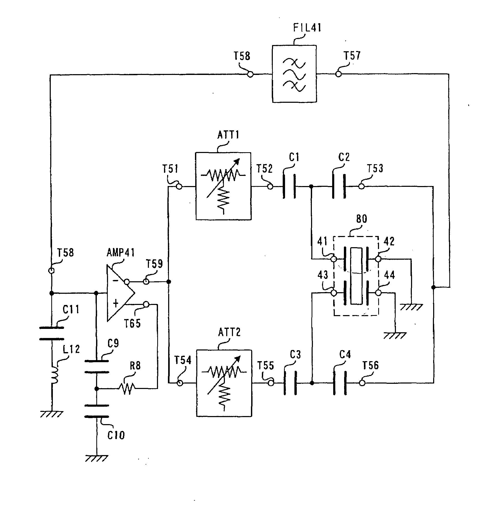
[0170]As shown in FIG. 13D, eight electrodes 71 to 74 and 71′ to 74′ are formed on the lower part 53. The configuration of the eight electrodes will now be described from a view point of operations thereof. The third embodiment of the present invention includes the twin-tuning fork structure in which four electrodes shown in FIG. 13C are respectively formed on four surfaces of the upper part 52 and eight electrodes shown in FIG. 13D are formed on four surfaces of the lower part 53. The four electrodes of the upper part 52 are connected to the external electrodes 41 and 42 as shown in FIG. 13C. Th...


PUM


Abstract

There is provided a resonance circuit using piezoelectric vibrator such as a quartz resonator, a coil, a capacitor, or an element equivalent to them in combination. When two resonance circuits having different resonance frequencies are combined, it is possible to configure an oscillation circuit and a filter capable of freely adjusting the frequency characteristic by utilizing the phenomenon that by changing the excitation current or voltage of the respective resonance circuits independently from each other, antiresonance frequency of the entire composite resonance circuit can be changed.

Description

TECHNICAL FIELD[0001]The present invention relates to a complex resonance circuit including a piezoelectric vibrator such as a quartz resonator, a coil, a capacitor, and an element equivalent to them. The present invention also relates to an oscillation circuit and a filter using the complex resonance circuit.BACKGROUND ART[0002]A resonance circuit including a coil, a capacitor, and a circuit element equivalent to them is used in various electronic circuits. The resonance circuit is often required to have a resonance frequency controlling function. A resonance frequency of the resonance circuit is typically controlled by changing either one or both of an inductance value of the coil and a capacity (capacitance) value of the capacitor. As one of many important electric circuits utilizing a resonance behavior of the resonance circuit, an oscillation circuit and a filter have been known. The oscillation circuit and the filter are electronic parts indispensable for operating, for exampl...

Claims


Application Information

Patent Timeline
IPC IPC(8): H03B5/32H03H9/205H01L41/047
CPCH03B5/30H03B5/36H03B28/00H03H9/25H03J3/00H03H9/56H03H9/566H03H9/6433H03H2003/0464H03H9/545
Inventor HIRAMA, KOICHI
Owner HIRAMA KOICHI
Why Eureka
Try Eureka