[0005]The traditional method of cooling an electronic device is by using a fan to circulate air around the electronic device, and thus remove thermal energy. Unfortunately, the problems associated with fan-type technology are multiple, including a relatively low
cooling efficiency, a bulky power source and a limited functional size. Furthermore, in applications such as
tower mounted infrastructures, fan-type technology is undesirable because of the weight of fan technology and further because fan failure can have extremely disadvantageous effects. Thus,
passive cooling is most desired in such applications. Methods have developed to replace fan-type cooling devices which are both smaller and located in the immediate vicinity of the electronic device needing to be cooled. One purpose of the present invention is to provide a
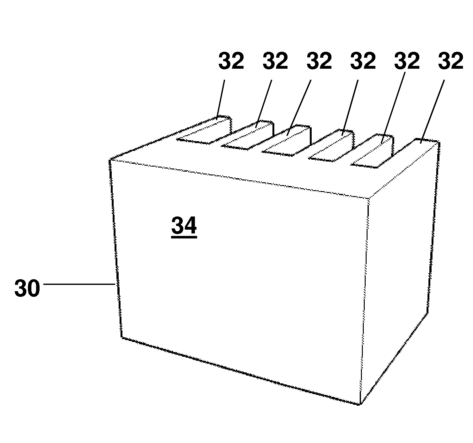
heat management device which can eliminate the use of fans, but more generally, it is to provide a more efficient heat sink for use in situations where heat sink performance is limited by spreading in the base of the heat sink, allowing reduction of
airflow requirements or lower
thermal resistance for a given
airflow or in
natural convection.
[0006]One popular method for the dissipation of heat from modern
electronics is an aluminum heat sink. While aluminum does not have the thermal
conductivity of
copper, it is significantly lighter in weight (having a density of about 2.7 g / cc as opposed to 8.9 g / cc for pure
copper). Thus, for portable applications like
laptop computers or stationary applications where weight supporting structures are undesirable, aluminum has been preferred. In addition, aluminum heat sinks tend to be substantially less expensive than
copper heat sinks.
[0007]Generally, aluminum heat sinks are formed by one of two methods,
extrusion and
die casting. Extruded aluminum heat sinks are produced by forcing molten aluminum through a precision die to produce an article of constant cross-section. Extruded aluminum heat sinks have a thermal
conductivity of about 220 W / m-K, which is useful for many
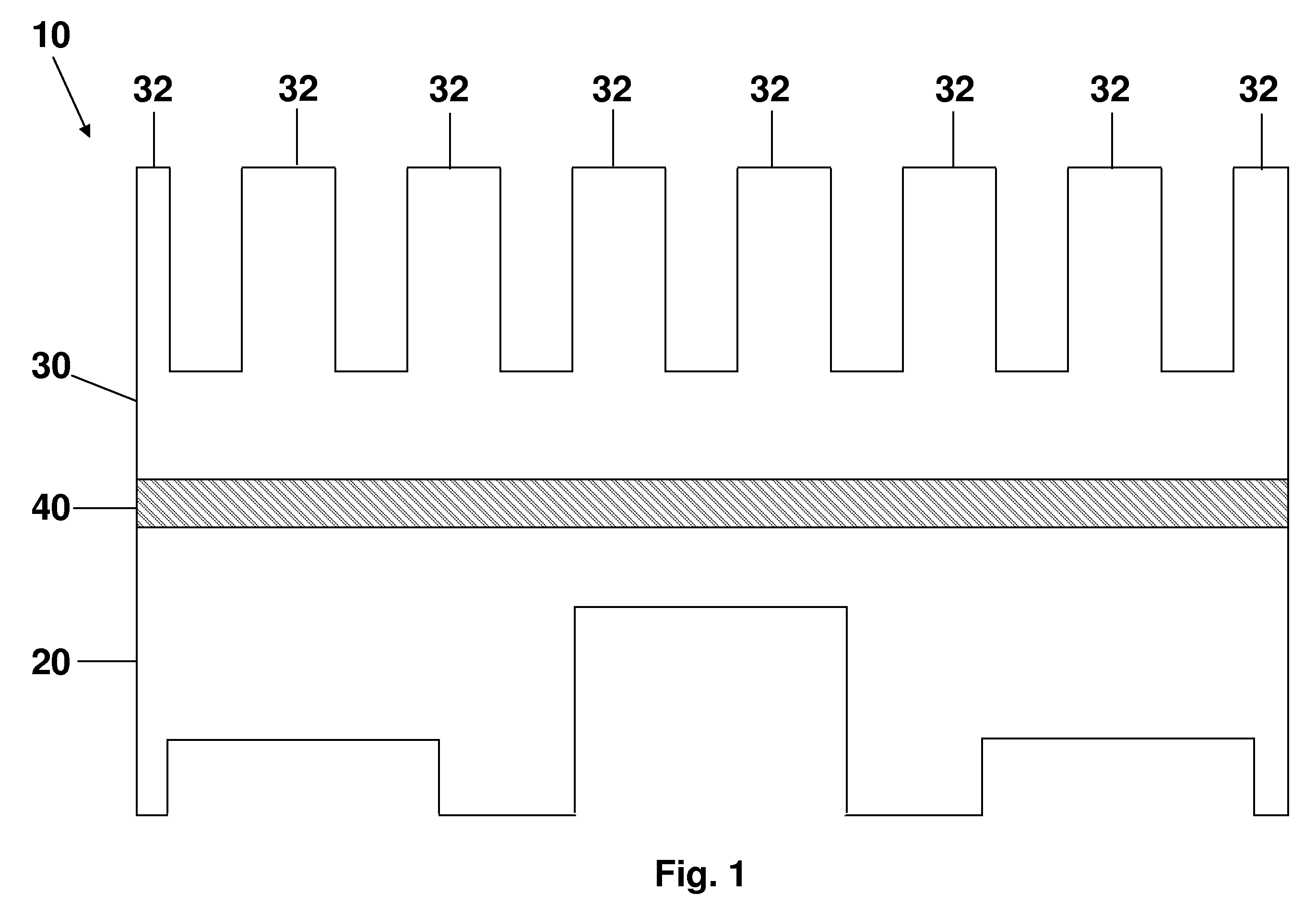
thermal dissipation applications. However, extruded aluminum heat sinks are disadvantageous when the non-finned surface of the heat source has a complex shape. In other words, when it is desired to position the heat sink such that it sits on multiple components, the surface of the heat sink
mating with the electronic components must conform to the differing profiles of the various components. A heat sink with a flat mating profile would not be adequate, but
machining or otherwise forming a complex profile into an extruded aluminum heat sink is an expensive and time-consuming exercise.
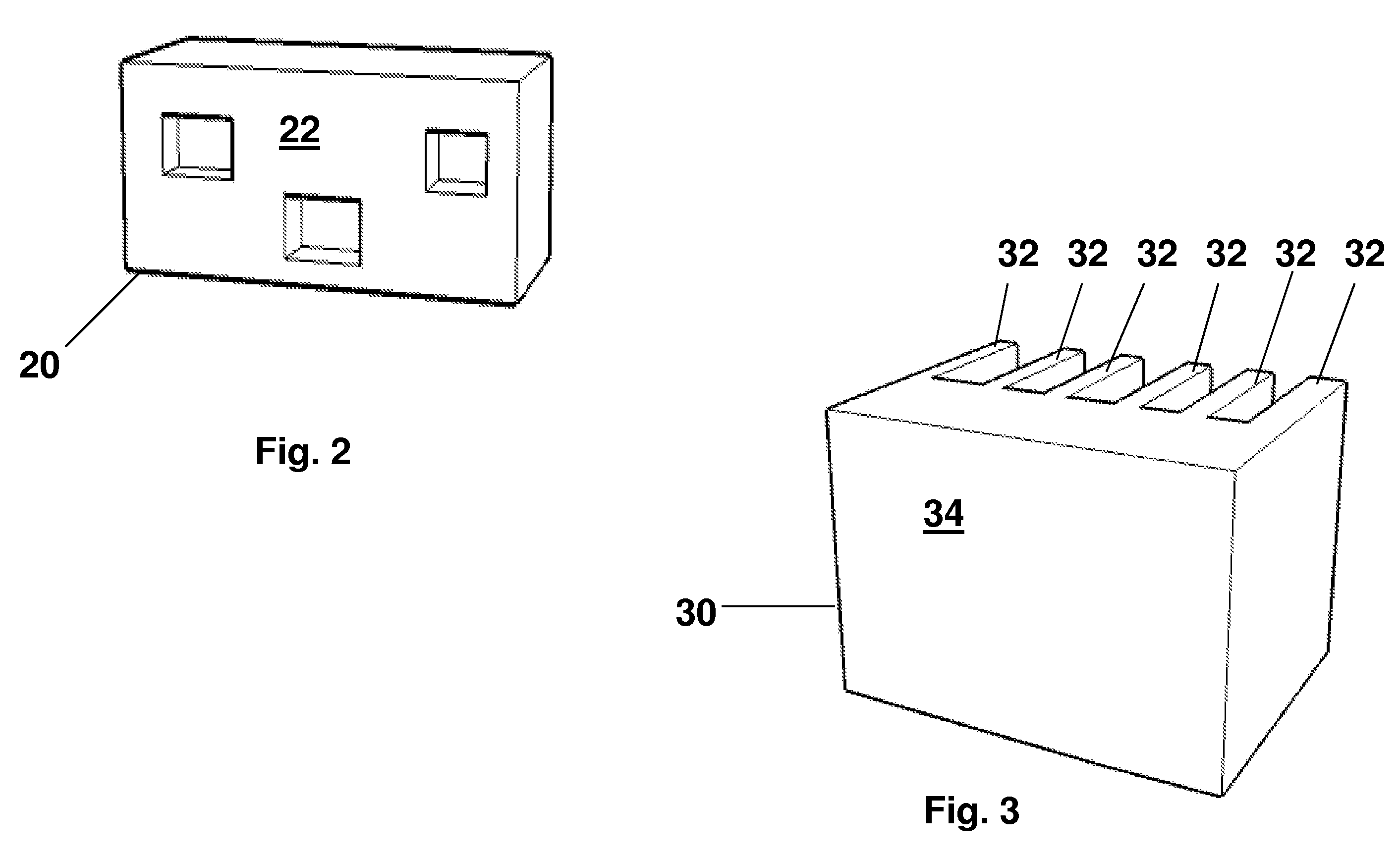
[0008]Heat sinks formed of die cast aluminum or
magnesium (or alloys thereof) can solve this problem, because
die casting can be used to form a heat sink with a complex
surface pattern. Die cast aluminum heat sinks are formed by injecting molten aluminum into a steel mold or die under
high pressure. While the use of die cast aluminum heat sinks can provide a mating surface having complex shapes in a cost effective manner, the thermal conductivity of cast aluminum heat sinks is often only about 100 W / m-K or lower, much less than desirable for most electronic thermal management application and less than half that of extruded aluminum heat sinks.
[0009]What is desirable, therefore, is a way to leverage the relatively high thermal conductivity of extruded aluminum heat sinks with the flexibility of shape of die cast aluminum heat sinks.
[0010]An additional method of managing thermal energy is through
graphite-based components which offer thermal conductivity comparable with or better than copper or aluminum but at a fraction of the weight while providing significantly greater design flexibility.
Graphite-based thermal management products take
advantage of the highly directional properties of
graphite to move heat away from electronic components while having thermal conductivities substantially higher than typical aluminum alloys used for
heat management. Furthermore,
graphite is anisotropic making it more suitable for channeling heat in a preferred direction.

