Fuel Processor, Components Thereof and Operating Methods Therefor

Inactive Publication Date: 2008-06-19
WESTPORT POWER
View PDF41 Cites 16 Cited by
  • Summary
  • Abstract
  • Description
  • Claims
  • Application Information

AI Technical Summary

Benefits of technology

[0065]The combined reactant stream can be directed past a bluff body into the reaction chamber where it is converted to the product stream. The bluff body can modify the flow characteristics of the combined reactant stream as it enters the reaction chamber. For example, it can increase t

Problems solved by technology

Flashback is uncontrolled combustion that can occur and propagate back from the combustion zone into to the mixing zone in the fuel processor.
However, such “active” reactant metering systems, with multiple moving and interconnected components, typically add to the overall complexity and cost of the system; reduce system reliability and durability; increase the likelihood of fluid leakage; and slow the dynamic response time of the fuel processor.
Conversion of liquid fuels, especially heavy hydrocarbons, can be difficult due to the various components that make up the fuel that react at different temperatures and rates.
Inadequate vaporization and mixing of the fuel with the oxidant stream can lead to localized fuel-rich conditions, resulting in the formation of coke or soot (carbon), and can also adversely affect the fuel conversion efficiency.
Chemical decomposition of the fuel can also lead to carbon formation starting at temperatures as low as about 200° C. Carbon deposits can impede the flow of gases in the fuel processor and downstream devices, increasing the back pressure in the system.
The temperature of the engine exhaust stream can reach over 600° C., but at such elevated temperatures there is a limited time in which to effectively vaporize and mix the two streams before undesirable carbon forming reactions will start to occur.
Furthermore the wide spray pattern can cause fuel to be sprayed onto the interior walls of the fuel processor creating a “wall wetting” effect that can create undesirable localized fuel-rich conditions.
Prior devices that have been use

Method used


Image

  • Fuel Processor, Components Thereof and Operating Methods Therefor
  • Fuel Processor, Components Thereof and Operating Methods Therefor
  • Fuel Processor, Components Thereof and Operating Methods Therefor

Examples


Embodiment Construction

)

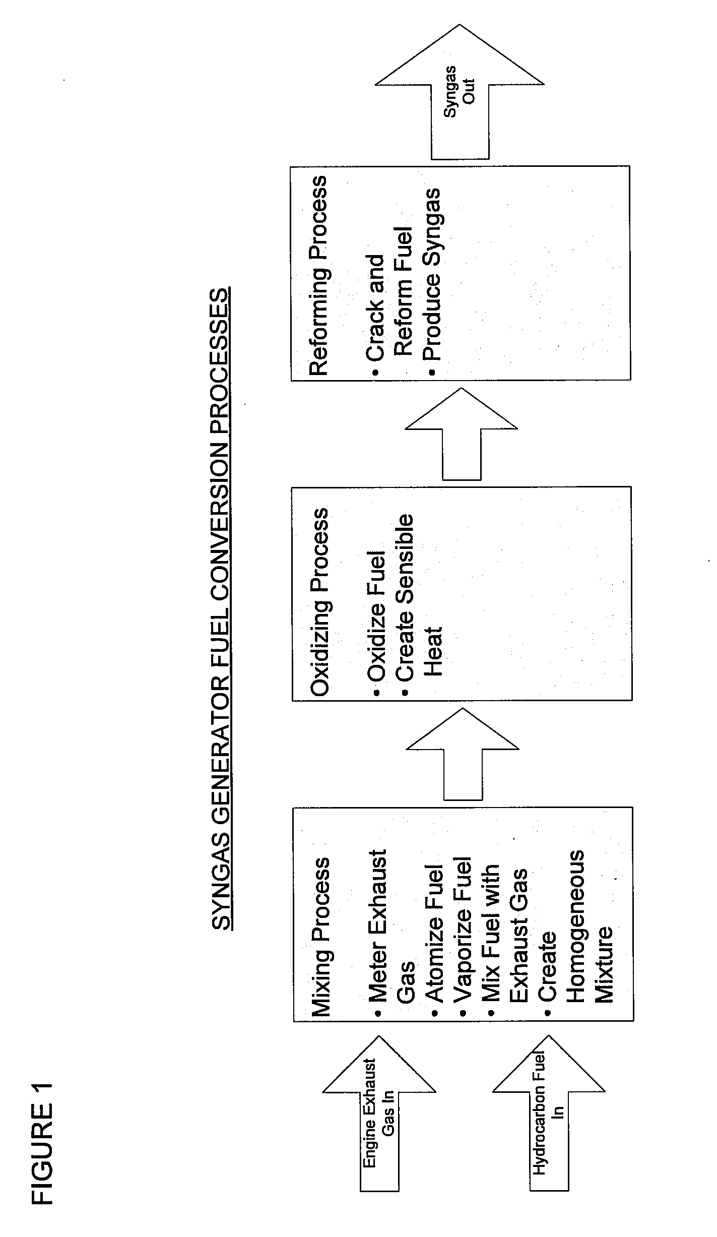
[0084]FIG. 1 illustrates a typical syngas generator (SGG) fuel conversion process, and is described above.

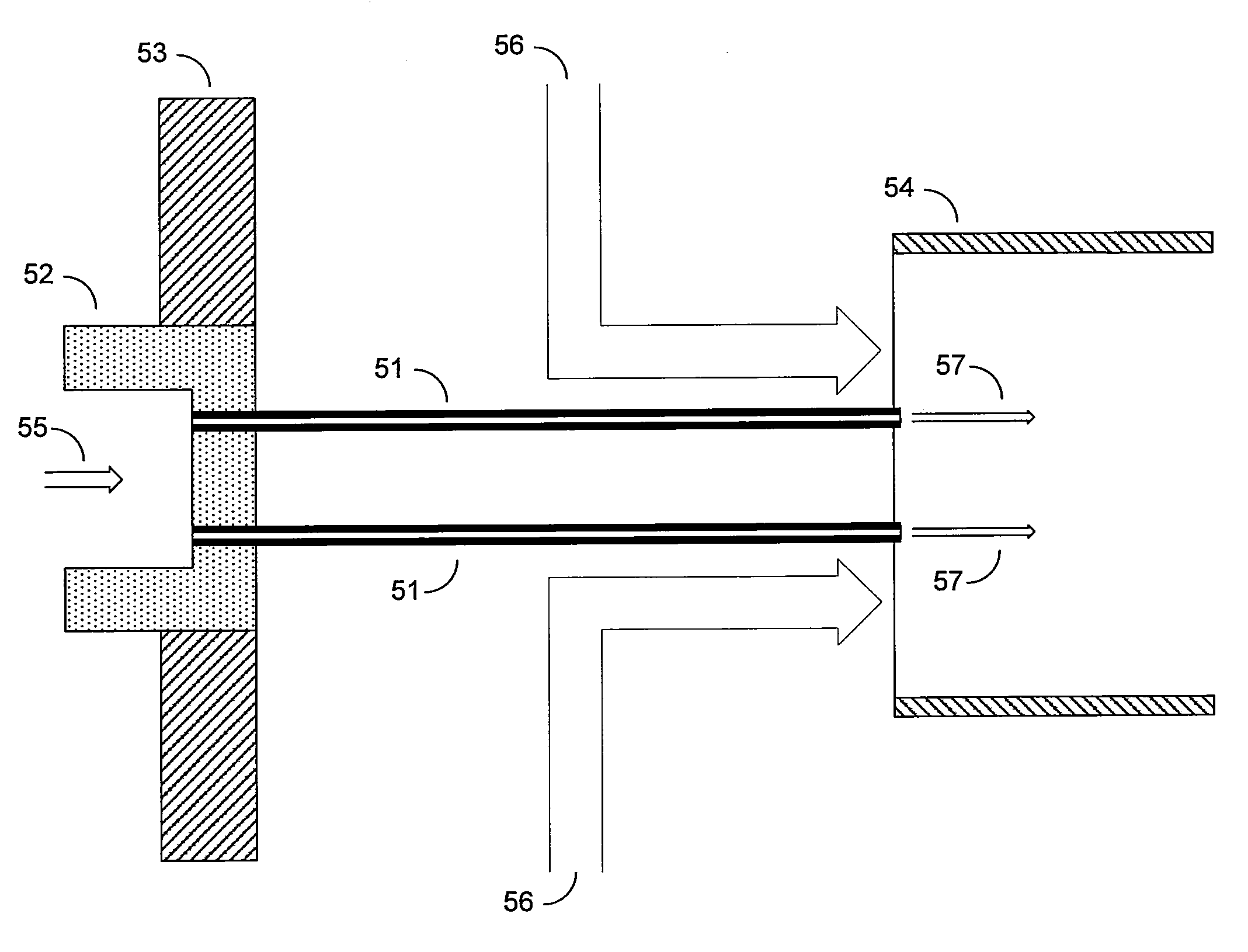
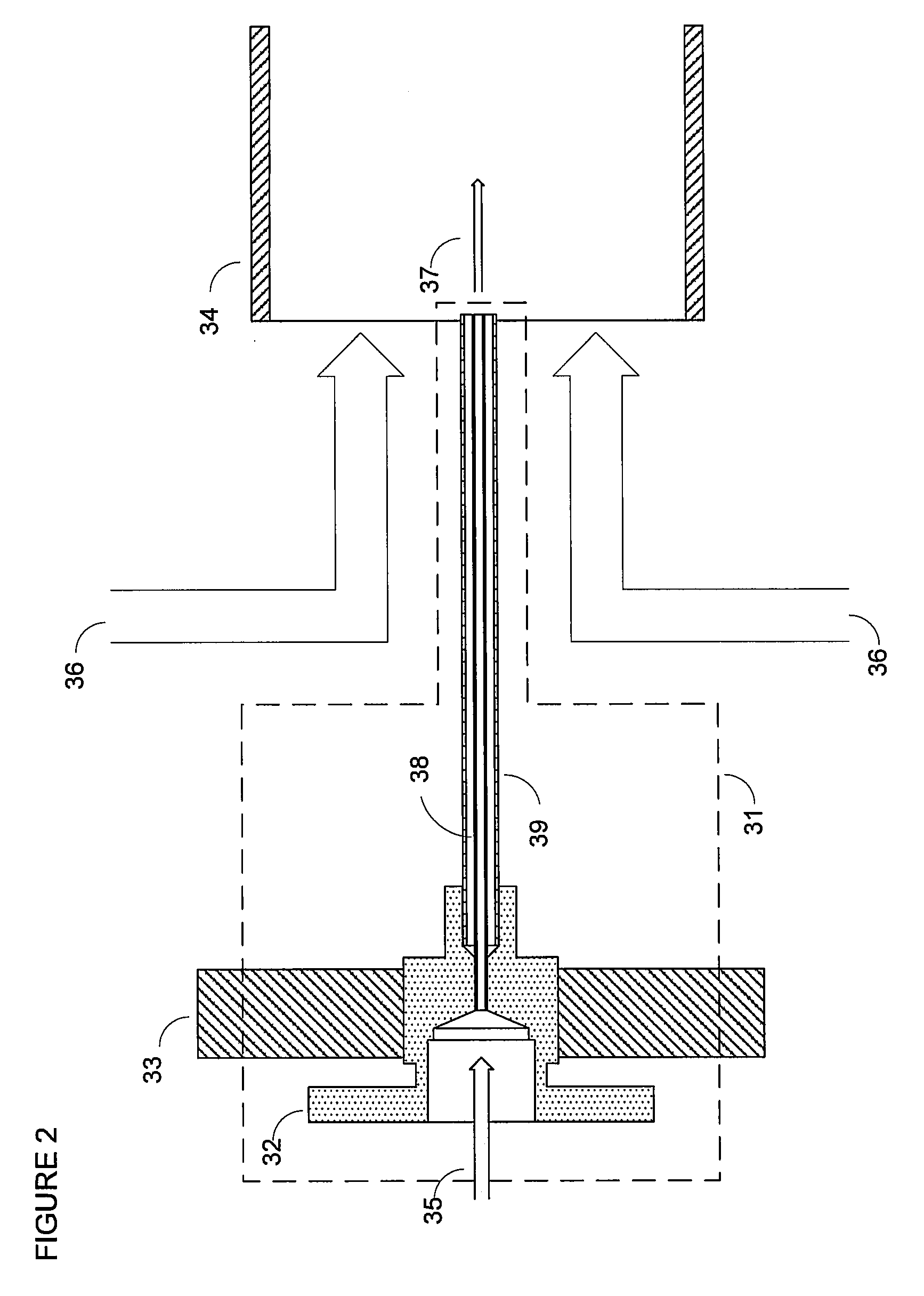
Embodiments Comprising a Fuel Introduction Tube

[0085]The present apparatus comprising a fuel introduction tube is particularly suited for introducing liquid fuels into hot oxygen-containing gas streams for downstream chemical conversion in a fuel processor. In situations where the temperature of the hot gas stream exceeds the boiling point of the liquid fuel at least some of the time during operation of the fuel processor, preferably the fuel introduction tube comprises thermal shielding. Similarly, methods of introducing a liquid fuel into a hot oxygen-containing gas stream comprise utilizing a fuel introduction tube as described herein. The fuel introduction tube can be passively or actively thermally shielded to reduce boiling of the fuel within the introduction tube, and preferably to maintain the liquid fuel stream below its boiling point within the fuel introduction tube....


PUM

PropertyMeasurementUnit
Fractionaaaaaaaaaa
Angleaaaaaaaaaa
Pressure dropaaaaaaaaaa

Abstract

Fuel processors include at least one of a fuel introduction tube, a critical flow venturi and/or a heat exchanger along with other components. Such fuel processors are particularly suitable for use in engine system applications where a liquid fuel is introduced into an oxidant stream comprising hot engine exhaust gas, for downstream conversion in the fuel processor to produce a hydrogen-containing gas stream, such as a syngas stream.

Description

CROSS-REFERENCE TO RELATED APPLICATION(S)[0001]This application is related to and claims priority benefits from U.S. Provisional Patent Application Ser. No. 60 / 864,319 filed Nov. 3, 2006, entitled “System And Method For Introducing A Fuel Stream Into An Engine Exhaust Stream”; Ser. No. 60 / 864,240 filed Nov. 3, 2006, entitled “Syngas Generator With Metering, Mixing And Flashback Arresting Device”; Ser. No. 60 / 864,248 filed Nov. 3, 2006, entitled “System And Method For Mixing A Fuel Stream And An Engine Exhaust Stream In A Fuel Processor”; Ser. No. 60 / 915,116 filed May 1, 2007, entitled “Syngas Generator”; and Ser. No. 60 / 954,803 filed Aug. 8, 2007, entitled “Syngas Generator”, each of which is hereby incorporated by reference in its entirety.FIELD OF THE INVENTION[0002]The present invention relates to fuel processors for producing a hydrogen-containing gas stream. The improved fuel processor includes at least one of a fuel introduction tube, a critical flow venturi or a heat exchange...

Claims


Application Information

Patent Timeline
IPC IPC(8): C01B3/02B01J19/00C01B31/18F01N3/00C01B32/40
CPCB01F3/04Y02T10/121B01F5/0652C01B3/366C01B2203/0255C01B2203/1235C01B2203/1276F01N3/0253F01N3/206F01N2240/30F01N2610/04F01N2610/05F02B3/06F02M25/12F02M27/02F23C13/06F23D14/64F23D2207/00F23J15/025F23L7/007F23L15/04F23M5/00F23M9/02Y02E20/344B01F5/0646Y02E20/34Y02T10/12B01F23/20B01F25/433B01F25/4335
Inventor JOHANNES, ERIK PAULNEELS, JACOBUSLI, XUANTIANSEDERQUIST, RICHARD ALLAN
Owner WESTPORT POWER
Why Eureka
Try Eureka