
Carrier for electrophotographic developer, image forming method, and process cartridge

a technology for electrophotographic developers and carriers, applied in the field of carriers for electrophotographic developers, can solve the problems of excessive increase of development properties of developers, degraded carrier adhesion of carriers that are stirred with toners within developing containers, and increase in image density, so as to reduce image density, increase charge amount, and prevent carrier adhesion

Inactive Publication Date: 2008-06-26
RICOH KK
View PDF8 Cites 24 Cited by
  • Summary
  • Abstract
  • Description
  • Claims
  • Application Information

AI Technical Summary

Benefits of technology

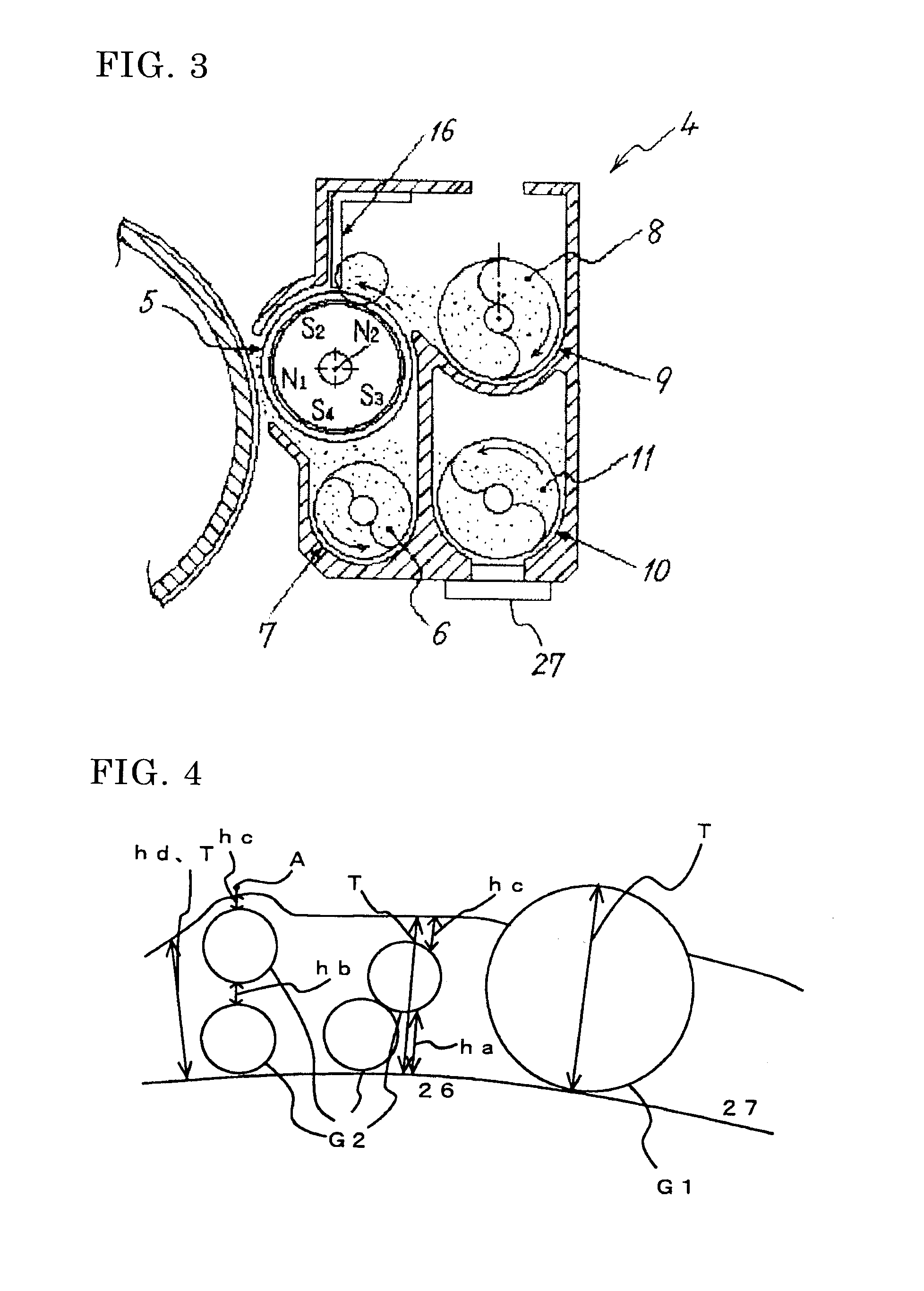
[0062]The carrier for electrophotographic developer according to <2> can provide a carrier for two-component developers, in which the two-component developer is used for developing devices having a developer supplying conveying path, a developer collecting conveying path, and a developer stirring conveying path, as shown in the descriptions below including Examples, the two-component developer can be far from occurrences of nonuniform image density or density decrease at development even under insufficient stirring at the developer stirring conveying path, operating conditions can take an allowance still further in terms of charging stability in the trickle development system for a long period, and the carrier can prevent color smear due of the toner even when contacting with the toner in the trickle development system for a long period or scraping of coating film occurs due to prolonged usage, furthermore an electrophotographic developer is provided, and also an image forming method, an image forming apparatus, and process cartridge are excellently and effectively provided on the basis of the developer. Furthermore, in cases of two-layer coating carrier containing a conductive fine particle, in which the conductive coating layer is formed of a lower layer that includes tin dioxide and an upper layer that includes tin oxide and indium oxide, such a very excellent effect can appear that the change amount of resistance is smaller.
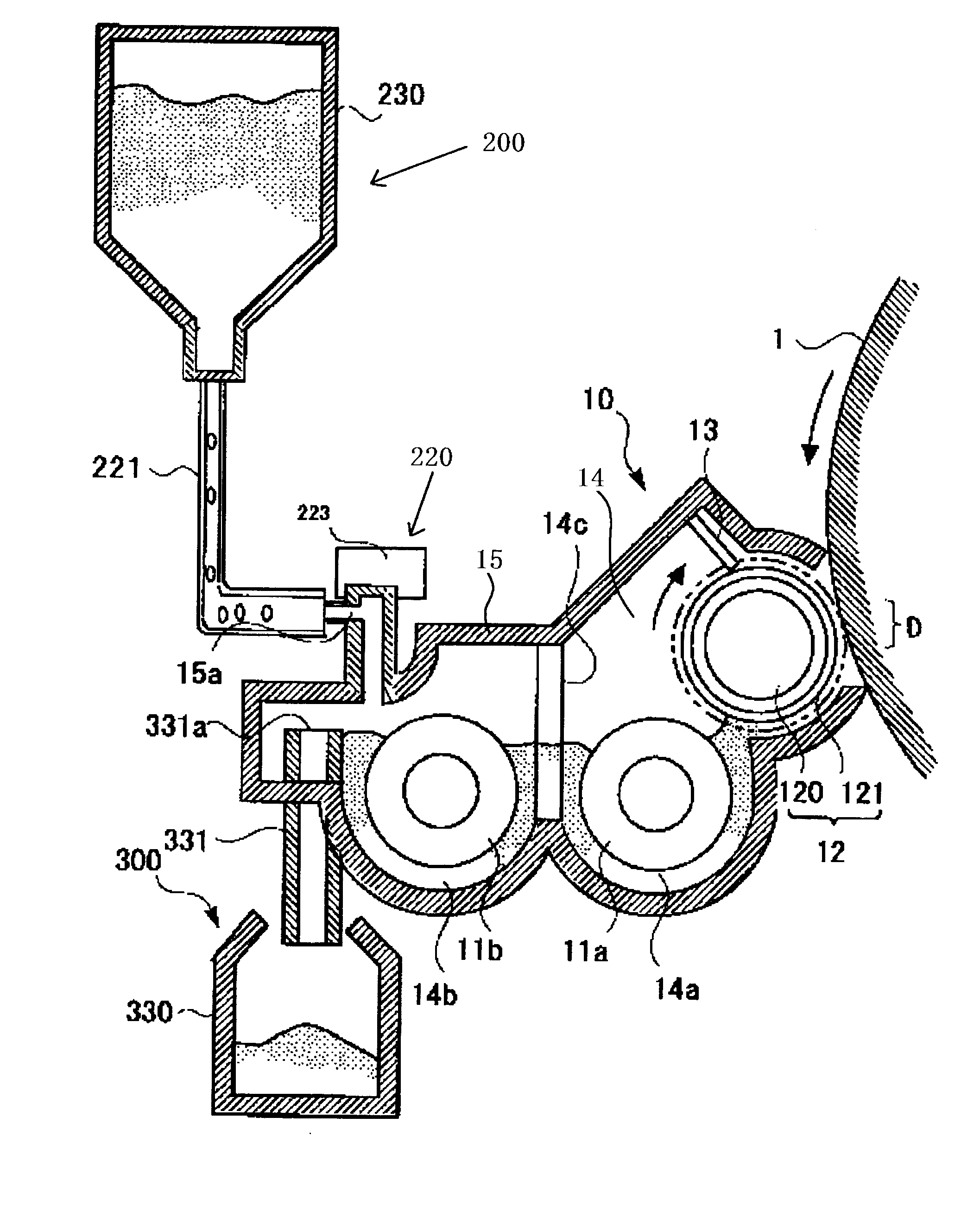
[0076]In accordance with the image forming apparatus according to <17>, the toner can be supplied in a condition that the toner amount supplied by the supplying device is stable and the amount of the toner remaining within the developer containing member is reduced, in addition to the effects of the image forming apparatus described above.

Problems solved by technology

Consequently, carriers that are stirred with toners within developing containers degrade along with increasing frequency of the stirring.
Specifically, such problematic phenomena occur as resin coating peels from carrier surface and toners adhere to carrier surface, as a result, such problems are induced as resistivity of carrier and charge amount of developer decrease gradually, developing property of developer excessively increases, image density increases, and fog is generated.
There exists hence a problem that toner concentration in the developer supplied to the developing roller decreases in the conveying direction toward the downstream of the conveying path to supply to the developing roller.
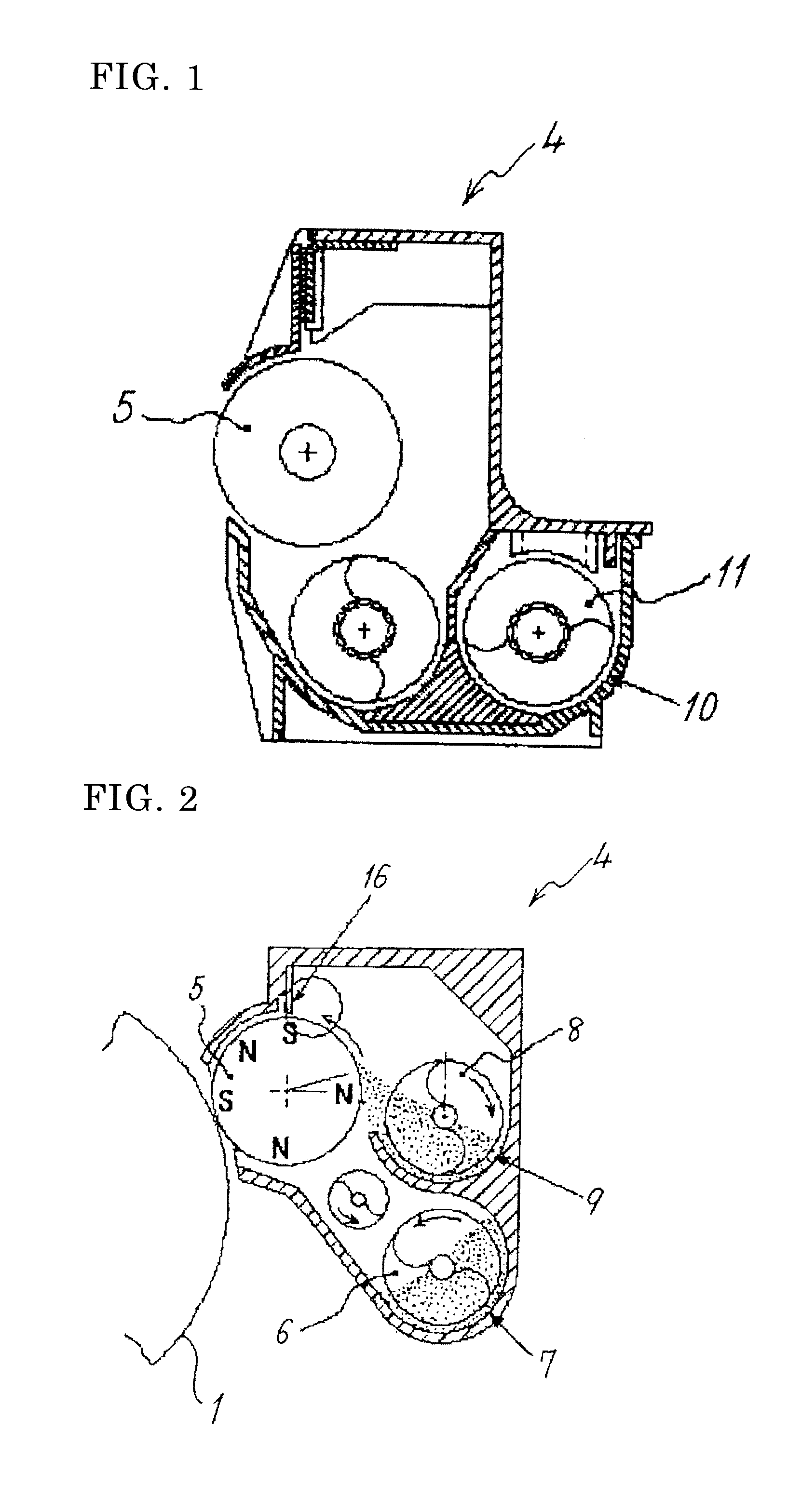
However, there is such a problem that image density is nonuniform and density decreases at developing step since the developer, which being supplied to the collecting conveying path 7, is immediately supplied to the supplying conveying path 9 and thus stirring is insufficient even when toner is supplied and the toner concentration is maintained appropriately.
This problem tends to be more noticeable as printing rate of images is higher in which toner concentration of collected developer is lower.
However, insufficient stirring within the stirring conveying path 10 may generate the nonuniformity of image density and the decrease of image density at developing step even in the developing device shown in JP-A No. 1-167260.
Consequently, carriers that are stirred with toners within developing containers degrade along with increasing the frequency of the stirring.
Specifically, such phenomena occur as resin coating peels from carrier surface and toners deposit on carrier surface, as a result, such problems are induced as resistivity of carrier and charge amount of developer decrease gradually, developing property of developer excessively increases, image density increases, and fog is generated.
However, the rate of degraded carriers increases little by little within the developing container along with using for a long period and it is difficult to suppress problems such as increase of image density, even in the developing device disclosed in JP-B No. 02-21591.
However, the carrier amount exchanged within developing devices changes with time while toner consumption varies; thus there arises a problem that image density tends to fluctuate due to variation of resistivity and / or charge amount of the developers within developing devices, in the methods disclosed in JP-A Nos. 03-145678 and 11-223960.
However, specific gravities are remarkably different indeed between carriers and toners, therefore, it is very difficult to supply sequentially supplying developers into developing devices without intermixing each other within a toner-supplying container as disclosed in JP-A No. 08-234550, where the supplying developers contain one of plural carriers having different physical properties and a toner; in addition, the amount of toners is large relative to carriers in developers, thus the carriers tend to degrade and stable images cannot be formed for a long period.
In addition, when coating amount of silicone coating layer to be coated on the carrier core material is merely increased in order to raise the resistivity of supplying carriers as described in JP-A No. 08-234550, the charge amount of carriers tends to decrease while the resistivity is raised, as a result, there arise such problems as reproducibility of images to be developed is impaired and background smear generates.
However, there still exist problems in durability and heat-resistance, and also such problems exist as occurrences of toner spent on carrier surface, unstable charge amount therefrom, toner fog, etc.
However, when such carriers are used in image forming apparatuses to form color images, it is likely that the carbon black migrates into color images to cause color smear though film scraping from carrier surface or separating the carbon black.
However, in recent years, there is a significant trend toward speeding up in the image forming apparatuses of electrophotographic systems described above, and stress on developers has been increasing dramatically in association therewith.
It is therefore difficult to completely prevent the color smear through migration of carbon black into images even by the proposals of JP-A Nos. 07-140723, 08-179570, and 08-286429.

Method used


Image

  • Carrier for electrophotographic developer, image forming method, and process cartridge
  • Carrier for electrophotographic developer, image forming method, and process cartridge
  • Carrier for electrophotographic developer, image forming method, and process cartridge

Examples


synthesis example 1

of Binder Resin

[0342]Seven hundred and twenty-four parts of an adduct of bisphenol A with 2 moles of ethylene oxide, 276 parts of isophthalic acid, and 2 parts of dibutyltin oxide were poured into a reactor vessel equipped with a condenser, a stirrer and a nitrogen gas inlet, and the mixture was allowed to react at 230° C. for 8 hours under normal pressure, then was further allowed to react under a reduced pressure of 10 to 15 mmHg for 5 hours, followed by cooling to 160° C.; 32 parts of phthalic anhydride was then added to the reactant and the mixture was allowed to react for 2 hours.

[0343]The reactant was then cooled to 80° C., which was allowed to react with 188 parts of isophorone diisocyanate in ethyl acetate for 2 hours to prepare an isocyanate-containing prepolymer P1.

[0344]Then 267 parts of the prepolymer P1 and 14 parts of isophorone diamine were allowed to react at 50° C. for 2 hours, thereby to prepare a urea-modified polyester U1 having a mass average molecular mass of 6...

preparation example 1

of Master Batch

[0350]

pigment: C.I. Pigment Yellow 15540 partsbinder resin: polyester resin A60 partswater30 parts

[0351]The ingredients described above were mixed in a Henschel mixer to prepare a mixture containing pigment agglomerate to which water being immersed. The mixture was kneaded for 45 minutes by twin rolls of which the surface temperature was set to be 130° C., then was milled by a pulvelizer into a size of about 1 mm Φ to prepare a master batch M1.

Toner Production Example A

[0352]Into a beaker, 240 parts of the solution of the binder resin B1 in ethyl acetate and MEK, 20 parts of pentaerythritol tetrabehenate (melting point: 81° C., melt viscosity: 25 cps), and 8 parts of the master batch M1 were introduced, then the mixture was stirred at 60° C. and 12,000 rpm by a TK-type homomixer to dissolve and disperse uniformly to prepare a toner ingredient liquid.

[0353]Into a beaker, 706 parts of deionized water, 294 parts of hydroxyapatite 10% suspension (Supertite 10, by Nippon C...

production example 1

[0367]

acrylic resin solution *1)2,130partsaminosilane *2)4partsconductive fine particle “a”1,500partstoluene6,000parts*1) solid content: 50% by mass*2) solid content: 100% by mass

[0368]The ingredients described above were dispersed for 10 minutes by a homomixer to prepare a liquid for forming resin layer. A ferrite particle having a volume average particle diameter of 35 μm was used as the core material of carrier, the resin solution described above was coated on the surface of the core material by use of Spira Coater (by Okada Seiko K. K.) under an atmosphere of 55° C. in a velocity of 30 g / min and dried so as to adjust the thickness “h” to 0.15 μm. The thickness of the layer was adjusted by the velocity of the liquid. The resulting carrier was calcined in an electric furnace at 150° C. for 1 hour, and was broken up using a screen of opening 100 μm after cooling, thereby to prepare a carrier I. The average thickness T was 0.20 μm.

[0369]The volume average particle diameter of the co...


PUM


Abstract

A carrier for electrophotographic developer that comprises a particle of core material and a coating layer that coats the particle of core material, wherein a toner and a carrier are supplied into a developing device where a toner and a carrier being contained, and the surplus developer within the developing device is discharged, a coating layer on at least one of the supplied carrier and the carrier contained in the developing device comprises a white conductive fine particle that includes tin dioxide and indium oxide on a base material.

Description

BACKGROUND OF THE INVENTION[0001]1. Field of the Invention[0002]The present invention relates to a carrier for electrophotographic developer of two-component developer, an image forming method and a process cartridge.[0003]2. Description of the Related Art[0004]In electrophotographic image forming apparatuses such as copiers and printers, a latent image is formed by exposing a light on a surface of uniformly charged image bearing members, a toner image is formed by developing the latent image, and the toner image is then transferred on transfer members such as recording paper. The transfer member bearing the toner image is passed through a fixing unit, and the toner is fixed on the transfer member by action of heat and / or pressure.[0005]The developing devices, for developing latent images on image bearing members in the image forming apparatuses, are classified into one-component developing type where the developing is carried out by use of a toner that contains a magnetic material ...

Claims


Application Information

Patent Timeline
IPC IPC(8): G03G15/08
CPCG03G9/113G03G9/1139G03G9/1131
Inventor NAGAYAMA, MASASHIKONDOU, TOMIOYAGI, SHINICHIROIWATSUKI, HITOSHI
Owner RICOH KK
Learn More