Method and system for providing a high definition triangulation system

a triangulation system and high-definition technology, applied in the direction of optical radiation measurement, instruments, measurement devices, etc., can solve the problems of damage to the detection unit, decrease of the depth of field, and range of optical signals of the light detection uni

Active Publication Date: 2008-07-10
ONTO INNOVATION INC
View PDF14 Cites 51 Cited by
  • Summary
  • Abstract
  • Description
  • Claims
  • Application Information

AI Technical Summary

Benefits of technology

[0080]Further, according to this embodiment, the positioning assembly may include: a laser diode holder plate for holding the laser diode; a collimator adjustment tube for holding the collimator lens; for each of three dimensions, at least one corresponding positioning element, the positioning elements allowing for precise positioning of the laser diode with respect to the collimator lens in each of the three dimensions independently, the preciseness of the positioning in the dimension along the collimator lens' axis being at least to within 0.75 microns, and the preciseness of the positioning in the other two dimensions being to within 2.2 microns; a protection sleeve; and a biasing element for biasing the laser diode holder plate in a direction towards the collimator lens.
[0081]Further, according to this embodiment, the at least one corresponding positioning element of each dimension may include a pair of opposing parts, where one of: (I) the pair of opposing parts of each dimension includes a threaded part and a biasing element, the positioning in each dimension being performed by screwing the dimension's corresponding threaded part in a direction that is opposed to a biasing direction of the dimension's corresponding biasing element; and (II) the pair of opposing parts of a first dimension includes the threaded part and the biasing part of (I), and the pair of opposing parts of each of the remaining dimensions is a pair of opposing threaded parts, the positioning in each of the dimensions for which the pair of opposing threaded parts are used being performed by repeated screwing and loosening of each of the pair of opposing threaded parts. A threaded part of a first one of the dimensions may be configured for threadable insertion into the collimator adjustment tube for moving the collimator lens against a biasing element of the dimension along the collimator lens' axis, and each of a threaded part of a second one of the dimensions and a threaded part of a third one of the dimensions may be configured for threadable insertion into the laser diode holder plate for moving the laser diode transverse to the movement of the collimator lens and against corresponding opposing parts, the two transverse movements being orthogonal to each other. The protection sleeve may be configured to be coupled to the collimator adjustment tube and to cover the threaded part of the first dimension after completion of the movement of the collimator lens along the collimator lens' axis to guard against inadvertent movement of the collimator lens along the collimator lens' axis.

Problems solved by technology

A continuing difficulty with current triangulation sensors used for surface and lead inspection in the semiconductor industry is the need to simultaneously obtain a very small diameter spot for high definition and a large measuring range in depth, or depth of field.
This tension exists because improving one of the spot size or depth of field necessarily requires sacrifice of the other, e.g., increasing numerical aperture decreases spot size but greatly decreases depth of field.
Another difficulty with current triangulation sensors is the range of optical signals the light detection unit may be required to handle in the case of a highly specular target object being imaged.
For example, because solder balls are very shiny, depending on the slope of the portion of the solder ball that is illuminated by the laser beam, light from the impinging laser beam may be reflected from a solder ball directly away from the detection unit's optics (so that the detection unit receives almost no signal from which to detect the z component) or directly towards the detection unit's optics (so that the signal is so strong that it may damage the detection unit).
Reduction of wavelength may cause increased difficulty in detecting the light properly, so that use of shorter wavelengths has been avoided in conventional triangulation systems because of reduced performance of the light detection unit.
The requirement that the detection unit magnification be near unity or greater and that a narrow triangulation angle of 20 to 30 degrees be chosen to avoid shadowing leads to difficulty in both properly focusing the light onto the surface of the light detection unit and having the light be absorbed rather than reflected.
Furthermore, when a PSD is used as the light detection unit light from such reflections may be reflected back to and upon the PSD surface by nearby wire bonds or other elements internal to the PSD package, which, due to the nature of the PSD, can lead to erroneous depth measurement because the PSD cannot differentiate between the original light received and light received via secondary reflections.
Absence such optimal positioning, the collimated laser beam may have various optical aberrations and might not focus to a small compact spot.
For example, with respect to the collimator axis, if the laser diode is more than a ¼ wavelength from the proper spot with respect to the collimator lens, the beam might not be properly collimated.
Absent such positional assembly, the beam may leave in an off axis direction and suffer from various aberrations such as coma.
Reduction of spot size by reducing F# may be problematic, since depth of field is typically thereby also reduced, even more so (as is explained below) than in response to a similar reduction in wavelength.
Nevertheless, between the two, one would be more inclined to reduce F# than wavelength, because reduction of wavelength results in increased error when analyzing signals obtained by light reflected from any part of an inspected object.
Further, according to this embodiment, the laser beam may produce a spot size that is smaller than 35 microns and that, because of its small size, results in at least one of (a) aberrations that cause a field tilt and curvature and (b) a sensitivity to such aberrations, which skews analysis by the processor.

Method used


Image

  • Method and system for providing a high definition triangulation system
  • Method and system for providing a high definition triangulation system
  • Method and system for providing a high definition triangulation system

Examples


Embodiment Construction

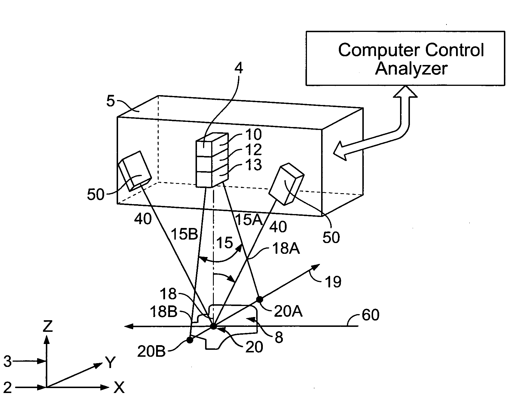
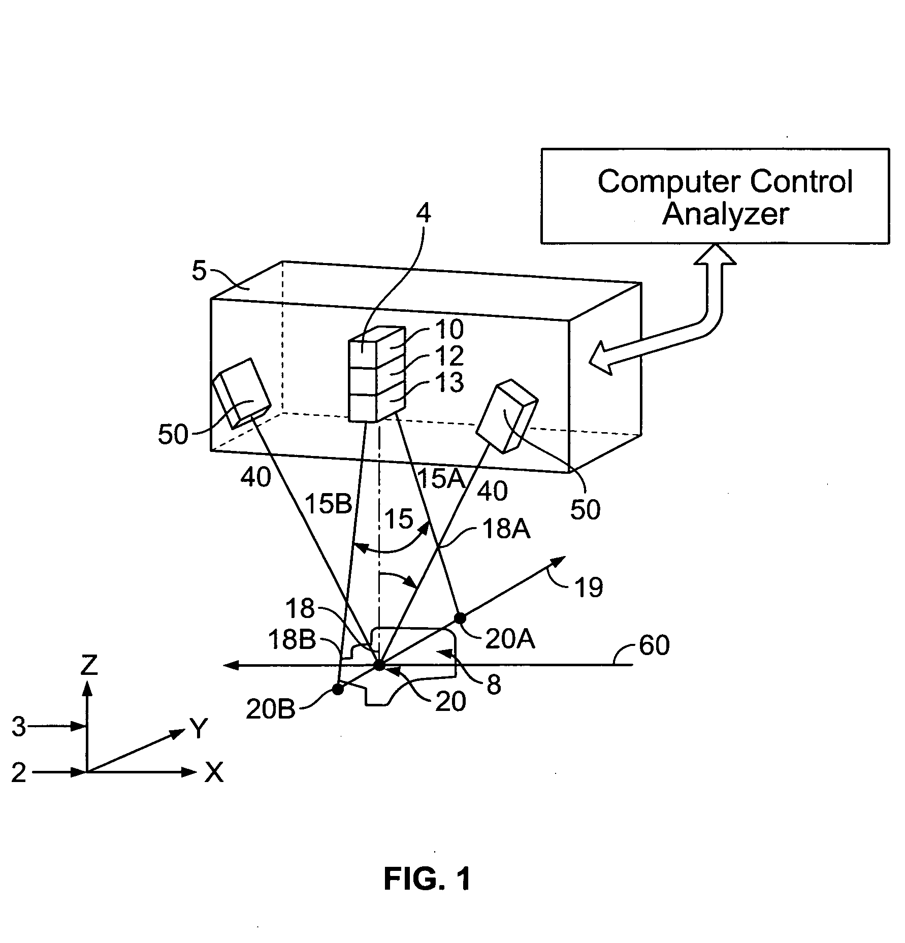
[0091]FIG. 1 is a schematic view of a 3-D data gathering portion of a scanning laser beam triangulation system, according to an example embodiment of the present invention, used, for example, to measure and inspect wafers and semiconductor devices. Although such systems often are capable of gathering 2-D data as is outlined in U.S. Pat. No. 6,291,816, issued to Liu, entitled “System and Method for Measuring Object Features with Coordinated Two and Three Dimensional imaging,” the disclosure of which is incorporated herein in its entirety by reference thereto, and in U.S. Pat. No. 5,859,924, issued to Liu et al., entitled “Method and System for Measuring Object Features,” the disclosure of which is incorporated herein in its entirety by reference thereto, the 2-D portion of the system is not described herein for the sake of clarity.

[0092]A scanning head 5 may be arranged to gather surface data from an object 8 at a nominal height 2 along the Z axis. The scanning head 5 may contain one...


PUM

PropertyMeasurementUnit
wavelengthaaaaaaaaaa

Abstract

A triangulation system including a laser beam, optics focusing the laser beam on an object, a light detection unit detecting light reflected from the object due to impingement of the beam on the object, and an arrangement for determining, based on the detected light, object feature dimensions. The wavelength of the laser beam may be shorter than of infrared radiation, which allows for a reduced spot size without significant loss of depth of field. So as to reduce aberrations or a sensitivity to aberrations due to the shortened wavelength, the system may include (i) a polarization dependent coating matching the index of refraction of an element of the light detection unit to that of air for a range of angles, (ii) tilted projection optics, (iii) a prism wavefront corrector, and/or (iv) a positioning assembly, which provides for increased precision in positioning the laser diode with respect to a collimator lens.

Description

CROSS-REFERENCE TO RELATED APPLICATION(S)[0001]This application claims priority to U.S. Provisional Application No. 60 / 857,715, filed Nov. 7, 2006, which is incorporated herein by reference in its entirety.FIELD OF THE INVENTION[0002]The present invention relates to a high definition triangulation system, and method for its use, adapted to measure or inspect surface features on objects, e.g., by determining the height of different parts of the objects, with higher precision and speed than conventional laser beam scanning triangulation systems.BACKGROUND INFORMATION[0003]Small features on semiconductor chips, packages, and wafers may be measured or inspected with scanning laser beam triangulation equipment. Such equipment has been previously described in the literature and in patents, such as U.S. Pat. No. 5,859,924, issued to Liu et al., entitled “Method and System for Measuring Object Features,” the disclosure of which is incorporated herein in its entirety by reference thereto.[00...

Claims


Application Information

Patent Timeline
Patent Type & Authority Applications(United States)
IPC IPC(8): G01J4/00G01B11/14G01N21/55
CPCG01B11/0608
Inventor STERN, HOWARDKRICHEVER, MARKLAWRENCE, MURRAYDRANNBAUBER, JAMES
Owner ONTO INNOVATION INC
Why Eureka
Try Eureka