Solid-state imager and solid-state imaging device

a solid-state imager and imaging device technology, applied in the direction of radio frequency controlled devices, television system scanning details, television systems, etc., can solve the problems of non-uniform sensitivity, modulation of readout circuits, and actualization of problems thereby caused, and achieve the effect of easy miniaturization of pixel siz

Inactive Publication Date: 2008-07-17
KK TOSHIBA
View PDF6 Cites 28 Cited by
  • Summary
  • Abstract
  • Description
  • Claims
  • Application Information

AI Technical Summary

Benefits of technology

[0014]Considering the above-described situations, the present invention provides a high-sensitivity and low noise color solid-state imager of a backside illumination type wherein the miniaturization of pixel size is easy.

Problems solved by technology

In recent years, further down sizing and larger numbers of pixels mounting have been required to such solid-state imagers, and the miniaturization of pixel sizes causes an important problem.
That is, compared with the reduction of plane size parallel to the surface of a semiconductor substrate accompanying the miniaturization of pixels, the reduction in the depth direction vertical to the surface of a semiconductor substrate has not been scaled at the same time, and problems caused thereby have been actualized.
Specifically, since the distance between the surface of the silicon substrate on which a photodiode is formed and the micro lens for optically expanding the aperture ratio is not reduced even if the size of the pixel region in the horizontal direction is reduced, a phenomenon known as “eclipse” or “vignetting” wherein a part of incident light is reflected by a metal wiring layer in the peripheral portion of the pixel region where incident light from the imaging lens diagonally enters occurs in the peripheral portion of the pixel region, and the non-uniformity of sensitivity is caused.
However, when long-wavelength light wherein the absorption coefficient of the silicon substrate is low, and the penetration length of incident light is large was imaged, there was a problem wherein the incident light passes through the rear surface side photodiode, reaches the surface side readout circuit region, and the operation of the readout circuit is modulated by electron-hole pairs generated there.
Consequently, the photodiode formed on the rear surface side could not be designed to be sufficiently large, and the effect of improving the aperture ratio of the photodiode by back-face was insufficient.
Specifically, the effect to improve the aperture ratio of the backside photodiode, or the effect to expand the area of the surface side readout circuit is not fully obtained.

Method used


Image

  • Solid-state imager and solid-state imaging device
  • Solid-state imager and solid-state imaging device
  • Solid-state imager and solid-state imaging device

Examples


Embodiment Construction

[0032]Embodiments of the present invention will be described in detail referring to the drawings. In the drawings shown below, the same parts will be denoted by the same numerals or characters, and repetitive description thereof will be omitted. The drawings are schematic, and the relation between thickness and planar dimensions, the thickness ratio of each layer, and the like are different from actual ones. Furthermore, some drawings contain parts having relations or ratios different from those in other drawings.

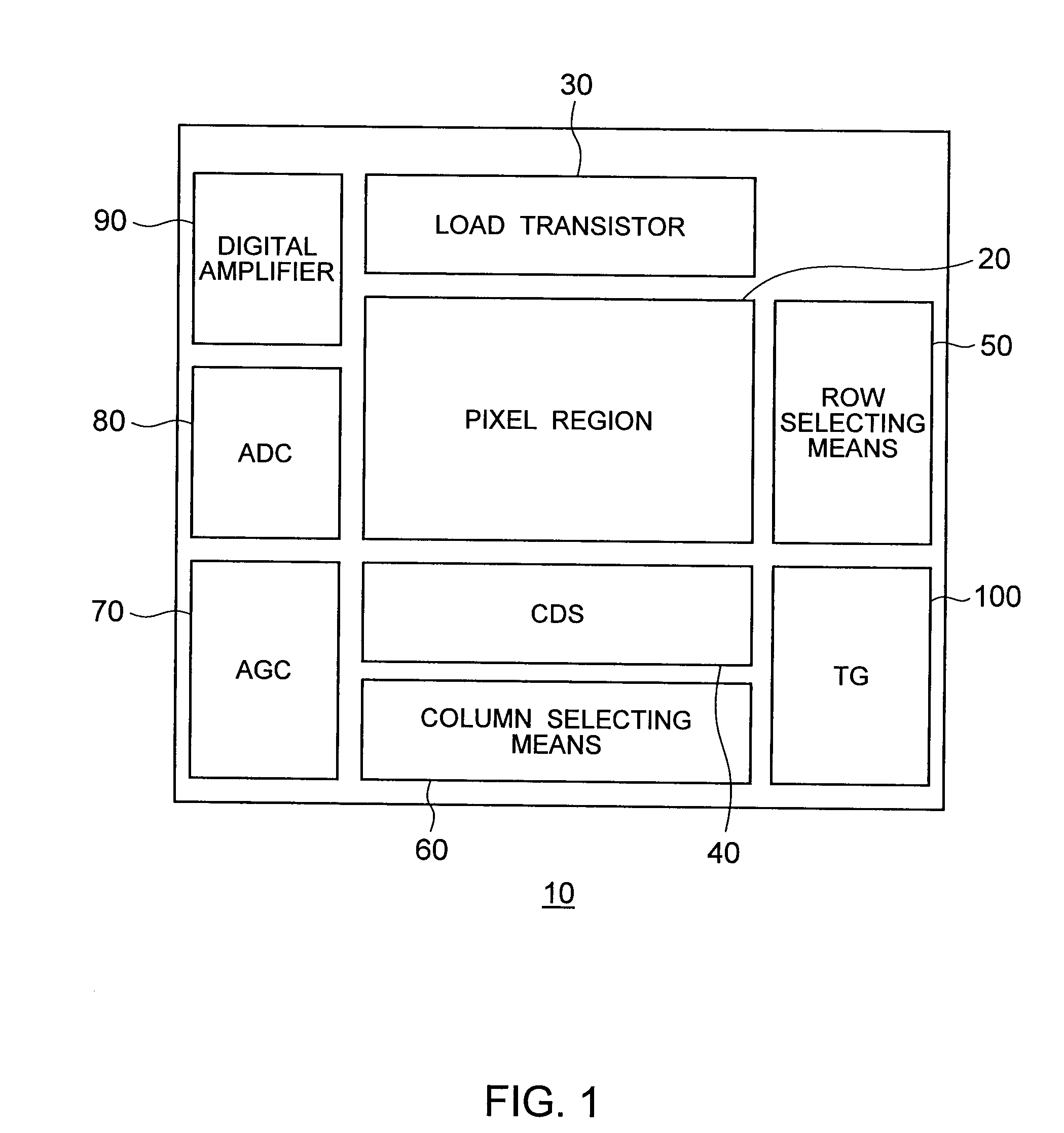
[0033]FIG. 1 is a block diagram for illustrating the schematic configuration of a solid-state imager 10 according to an embodiment of the present invention.

[0034]The solid-state imager 10 is formed by arranging a load transistor 30, a CDS (correlation double sampling) circuit section 40, row selection means 50, column selection means 60, an AGC (automatic gain control circuit) 70, an ADC (A / D converter) 80, a digital amplifier 90, a TG (timing generator) circuit 100 and the...


PUM


Abstract

There is provided a single-chip color solid-state imager of a backside illumination type having high sensitivity and low noise that facilitates the miniaturization of a pixel size. A pixel readout circuit is selectively disposed on a part of pixels of a readout block consisting of a plurality of pixels that share the pixel readout circuit.

Description

CROSS-REFERENCE TO RELATED APPLICATION[0001]This application is based upon and claims the benefit of priority from prior Japanese Patent Application No. 2007-4429 filed on Jan. 12, 2007 in Japan, the entire contents of which are incorporated herein by reference.BACKGROUND OF THE INVENTION[0002]1. Field of the Invention[0003]The present invention relates to a solid-state imager and a solid-state imaging device.[0004]2. Related Art[0005]Due to the diffusion of digital cameras, camera-mounted mobile phones and the like in recent years, demands for solid-state imagers have been increased. In particular, demands for CMOS solid-state imagers that can be manufactured using a CMOS process, which is an ordinary semiconductor manufacturing process, have been increased. In recent years, further down sizing and larger numbers of pixels mounting have been required to such solid-state imagers, and the miniaturization of pixel sizes causes an important problem.[0006]That is, compared with the redu...

Claims


Application Information

Patent Timeline
Patent Type & Authority Applications(United States)
IPC IPC(8): H04N3/14H01L27/146H04N5/335H04N5/357H04N5/369H04N5/374H04N5/378H04N9/07
CPCH01L27/14603H01L27/14609H01L27/14641H01L27/1464H01L27/14621
Inventor IIDA, YOSHINORIFUNAKI, HIDEYUKIHONDA, HIROTOFUJIWARA, IKUO
Owner KK TOSHIBA
Why Eureka
Try Eureka