Porous, degradable implant made by powder molding

a powder molding and implant technology, applied in the field of at least partially degradable implants, can solve the problems of increasing the thickness of the stent strut, the inability to inject or extrude powder mixtures, and the inability to meet the requirements of injection or extrusion molding, and achieve the effect of sufficient pore volum

Inactive Publication Date: 2008-07-24
CINVENTION AG
View PDF5 Cites 59 Cited by
  • Summary
  • Abstract
  • Description
  • Claims
  • Application Information

AI Technical Summary

Benefits of technology

[0011]It is one object of the present invention to provide a temporary implant capable of releasing active ingredients such as e.g. a drug or a marker etc. Another object of the invention is to provide implants with sufficient pore volume, whereby the pore sizes are controllable for incorporating large amounts of active ingredients.

Problems solved by technology

Such essentially dry mixtures are typically not suitable for injection or extrusion molding, since extrusion molding conditions could lead to grinding and / or melting of the particulate agglomerates.
The requirements for such implants are increasingly complex, because the material properties must meet the mechanical requirements on the one hand, on the other hand the provision of functions such as drug-release requires a significant drug amount to be released and bio-available.
This is particularly disadvantageous in biomedical implants, where anisotropic pore distribution, large pore sizes and a high degree of porosity are required, whereas simultaneously a high long-term stability with regard to biomechanical stresses is necessary.
For example, the conventional design of drug-eluting stents is based on non-porous scaffolds that have to be coated resulting in an increase of the stent strut thickness.
By increasing the thickness results in adverse properties, such as increasing the profile of the stents within the target vessels, which can limit the use to large vessels, or which can be correlated to mechanically induced, haemodynamic-related thrombosis

Method used


Image

  • Porous, degradable implant made by powder molding
  • Porous, degradable implant made by powder molding
  • Porous, degradable implant made by powder molding

Examples


example 1

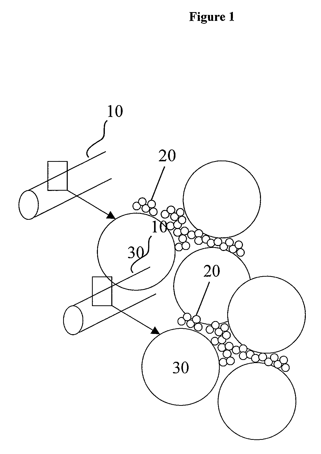
[0145]A slurry was produced using Mg nanoparticles and polyethylene beads. Mg nanoparticles was purchased from Metal Nanopowders Limited and polyethylene beads from Impag. The slurry was produced using 200 g of Mg nanoparticles (particle size D50 of about 50 nm) by adding 100 g acetone, stirring its for approximately 1 hour and adding 150 g of polyethylene beads. The slurry was homogenized for another 90 minutes.

example 2

Molding of Discoid Implants

Rapid Heating

[0146]A standard cylindrical hollow mold made out of stainless steel was used with an inner diameter of 3 cm and a length of 8 cm. The slurry of example 1 was filled into the mold until ⅘ of the volume was filled and compacting was carried out by using a standard floating mold die press to form a green body. Subsequently, a compaction pressure of 20 MPa was applied for 40 seconds, then repeating the cycle two further times. The green body comprised a discoid type mold with a diameter of 2.8 cm and a height of 2.5 cm. It was further dried at room temperature for 1 hour and then put into a standard tube reactor. The green body was sintered with a heating ramp of 20 K / min at 600° C. for 4 hours and then cooled down to room temperature within 20 hours. The thermal treatment was carried out under a nitrogen atmosphere at a N2-flow rate of 1000 ml / min.

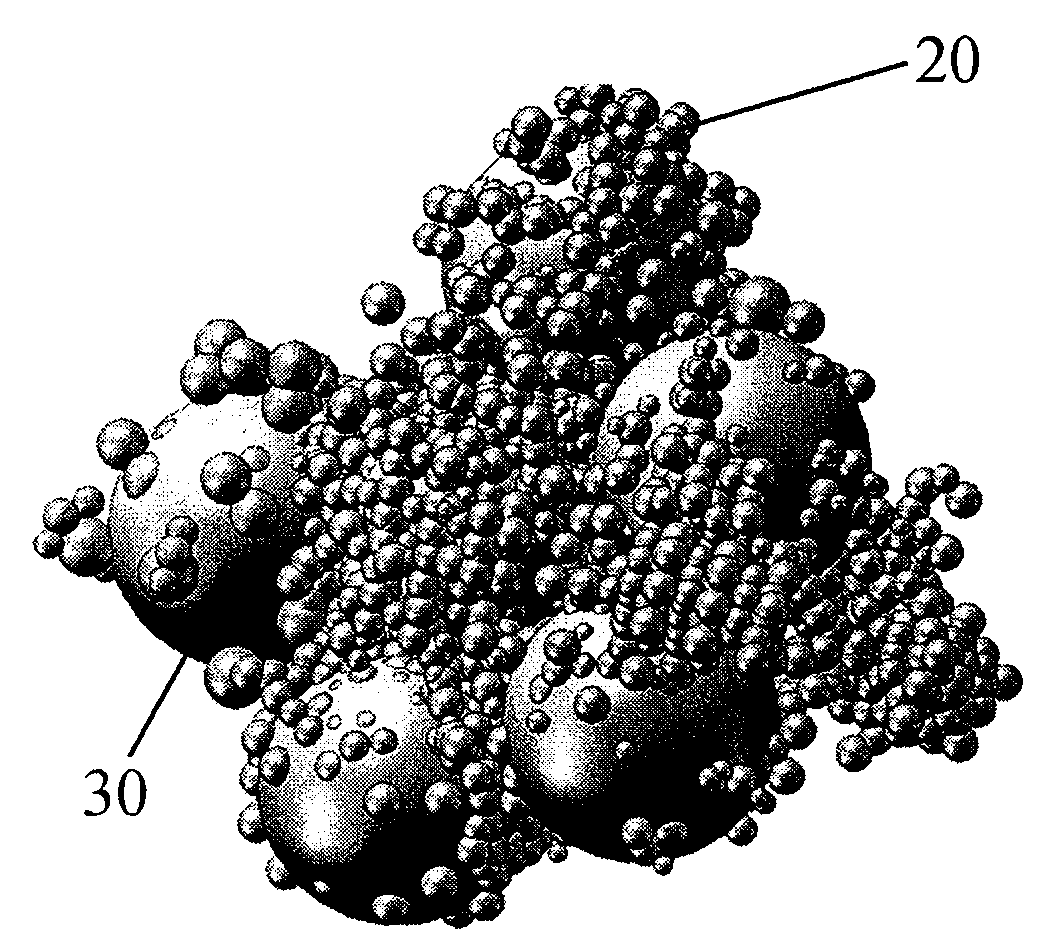
[0147]The molded body was cut to analyse the pore structure induced by the polyethylene bead filler...

example 3

Molding of Discoid Implants

Two Step Heat Treatment (Comparative Example)

[0148]The process of compacting was repeated according to example 2 with slurry of example 1 within the same mold. The green body comprised a discoid type mold with a diameter of 2.9 cm and a height of 2.6 cm. It was further dried at room temperature for 1 hour and then put into a standard tube reactor. The green body was thermally treated in two steps, first applying a heating ramp of 2 K / min up to 120° C., keeping 120° C. for approximately 1 hour, and then with the same ramp of 2K / min to 600° C. for 4 hours and then cooled down to room temperature within 20 hours. The thermal treatment was carried out under a nitrogen atmosphere at a N2-flow rate of 1000 ml / min.

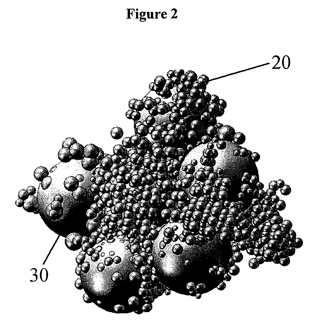
[0149]The molded body was cut to analyze the pore structure induced by the polyethylene bead filler. The molded body showed macroscopically a irregular surface structure. The fine structure was analyzed using FESEM. The FESEM image showed that the net s...


PUM

PropertyMeasurementUnit
compaction pressuresaaaaaaaaaa

Abstract

The exemplary embodiment of the present invention are provided which relate to at least partially degradable implants and methods for the manufacture thereof which can use powder molding techniques. For example, a suspension can be provided comprising a plurality of first particles of at least one organic polymer, a plurality of second particles of at least one metal-based material which is at least partially biodegradable in-vivo, and at least one solvent. The first and second particles can be substantially insoluble in the solvent. The suspension can be molded to form a green body comprising the first particles embedded in a matrix of compressed second particles. The first particles may be removed from the green body by thermally induced decomposition and/or evaporation. Further, the green body can be sintered to form the implant. The first particles may be removed during the sintering procedure.

Description

CROSS-REFERENCE TO RELATED APPLICATIONS[0001]The present invention claims priority of U.S. provisional application Ser. No. 60 / 885,697 filed Jan. 19, 2007, the entire disclosure of which is incorporated herein by reference.FIELD OF THE INVENTION[0002]The present invention is directed to at least partially degradable implants and methods for the manufacture thereof which use powder molding techniques.BACKGROUND OF THE INVENTION[0003]Implants are widely used as short-term or long-term devices to be implanted into the human body in different fields of application such as orthopedic, cardiovascular or surgical reconstructive treatments. Typically, implants are made of solid materials, either polymers, ceramics or metals. To provide improvements of engraftment or ingrowth of the surrounding tissue or adhesion, or to enable drug-delivery, implants have also been produced with porous structures. Different methods have been established to obtain either completely porous implants, particular...

Claims


Application Information

Patent Timeline
Patent Type & Authority Applications(United States)
IPC IPC(8): A61F2/02B22F3/11B22F1/107
CPCA61B17/866A61B19/54C22C33/0257C22C1/0408B29K2995/006A61B2017/00004A61B2017/00526A61C8/0012A61F2/0077A61F2/28A61F2/30767A61F2/44A61F2002/30062A61F2002/30677A61F2002/30957A61F2002/30968A61F2002/3098A61F2002/30981A61F2210/0004A61F2240/004A61F2250/0067A61F2310/00395A61F2310/00407A61F2310/00574A61F2310/0058A61F2310/00598A61F2310/0073A61F2310/00742A61F2310/00856A61F2310/0097A61L27/446A61L27/54A61L27/56A61L27/58A61L31/128A61L31/146A61L31/148A61L31/16A61L2300/00B22F1/0074B22F3/1121B22F2998/10B29C67/04B22F3/22A61B90/39A61F2/3094B22F1/107
Inventor ASGARI, SOHEIL
Owner CINVENTION AG
Why Eureka
Try Eureka