
Light diffuser plate surface emission light source apparatus and liquid crystal display

Inactive Publication Date: 2008-08-07
SUMITOMO CHEM CO LTD
View PDF3 Cites 9 Cited by
  • Summary
  • Abstract
  • Description
  • Claims
  • Application Information

AI Technical Summary

Benefits of technology

[0009]The present invention has been conceived with the technical background described above, and has an object of providing a light diffuser plate which is more lightweight and has sufficient strength and is not deformed by heat or humidity, and also has sufficient surface hardness and is also excellent in scratch resistance, and a surface emission light source apparatus and a liquid crystal display apparatus which are free from scratches of the light diffuser plate and have high quality, and are also lightweight.
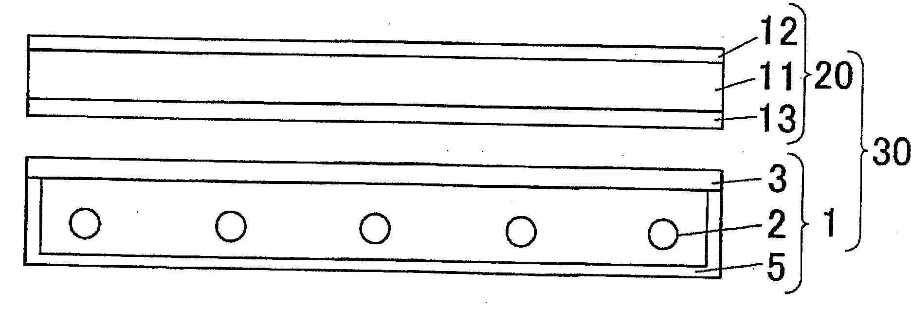
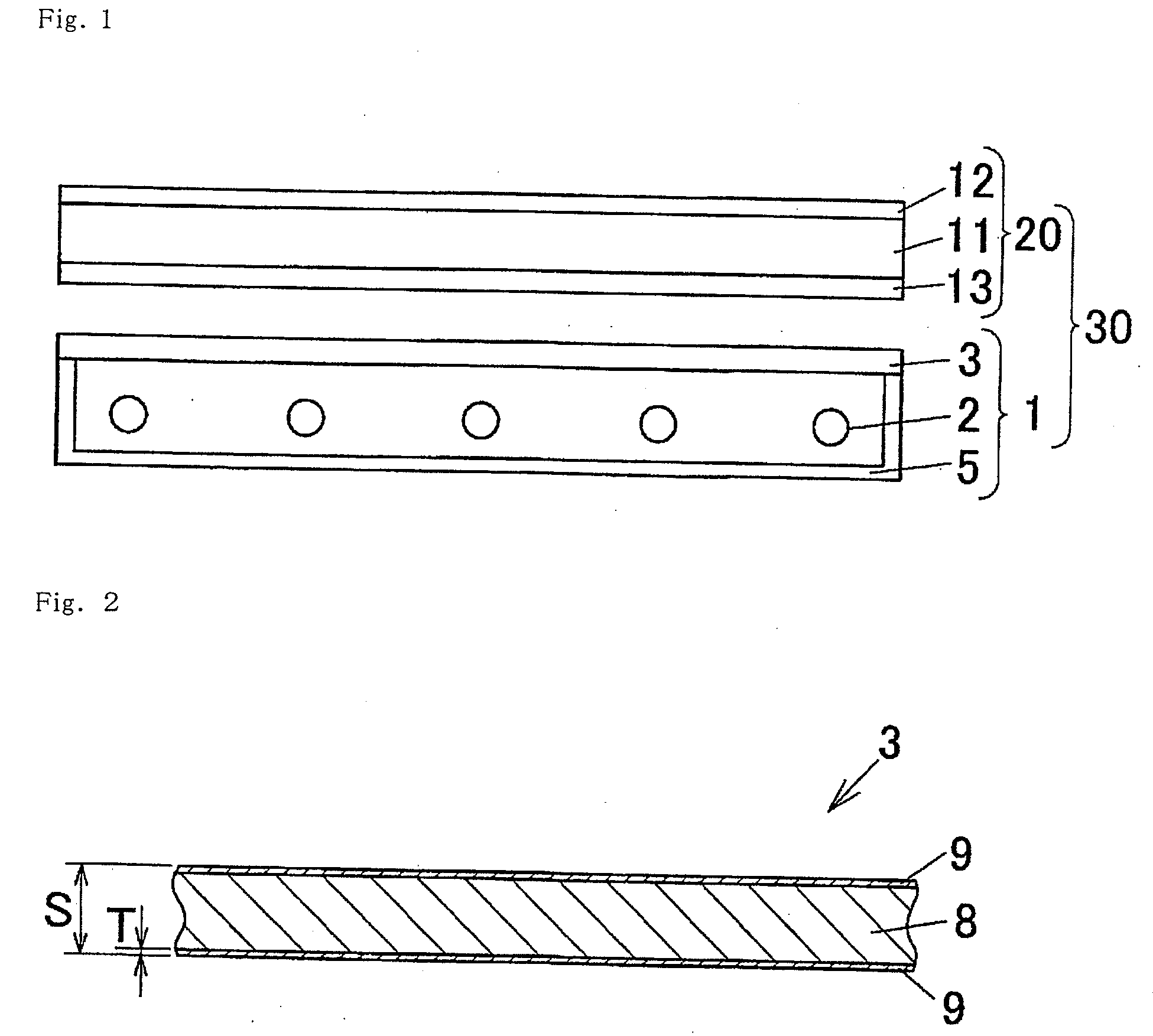
[0014]In the light diffuser plate of the invention of [1], since the base layer is made of a resin composition wherein light diffusing particles are dispersed in a propylene polymer, the light diffuser plate has a light diffusion function and is lightweight and is less likely to be broken, and is also excellent in heat resistance and humidity resistance and is not deformed by heat or humidity. Furthermore, the surface laminated integrally on one or both surfaces of the base layer is made of a resin composition containing particles having a volume average particle diameter of 10 to 200 μm in an amount of 5 to 50 parts by mass based on 100 parts by mass of a propylene polymer, and thus the light diffuser plate has sufficient surface hardness and is excellent in scratch resistance. Therefore, for example, even if the light diffuser plate is contacted with other components during assembly of a surface emission light source apparatus and a liquid crystal display apparatus using the light diffuser plate, the surface is less likely scratched, thus making it possible to provide a surface emission light source apparatus and a liquid crystal display apparatus which have high quality.
[0015]In the invention of [2], since the resin composition constituting the surface layer further contains an ultraviolet absorber in an amount of 0.1 to 5 parts by mass based on 100 parts by mass of the propylene polymer, light resistance of the light diffuser plate can be improved.
[0016]In the invention of [3], since the volume average particle diameter of the light diffusing particles is 0.5 μm or more and less than 10 μm, light diffusion performance can be further improved.
[0018]In the invention of [5], a surface emission light source apparatus, which is free from scratches of the light diffuser plate, and also has high quality and is lightweight, is provided.
[0019]In the invention of [6], a liquid crystal display apparatus, which is free from scratches of the light diffuser plate, and also has high quality and is lightweight, is provided.

Problems solved by technology

However, the above conventional light diffuser plate can not satisfy all these required characteristics.

Method used


Image

  • Light diffuser plate surface emission light source apparatus and liquid crystal display
  • Light diffuser plate surface emission light source apparatus and liquid crystal display

Examples


example 1

[0080]The above resin composition X was dry-blended, supplied to a first extruder having a screw diameter of 40 mm and melt-kneaded at a temperature of 210 to 250° C., and then the kneaded mixture was supplied to a feed block.

[0081]89.5 parts by mass of a polypropylene-ethylene copolymer (“D101” manufactured by Sumitomo Chemical Co., Ltd.), 10 parts by mass of acrylic polymer particles (particles B) (“XC1A” manufactured by Sumitomo Chemical Co., Ltd., volume average particle diameter: about 30 μm) and 0.5 parts by mass of LA31 (benzotriazole-based ultraviolet absorber manufactured by ADEKA Corporation) were dry-blended, supplied to a second extruder having a screw diameter of 20 mm and melt-kneaded at a temperature of 210 to 250° C., and then the kneaded mixture was supplied to a feed block.

[0082]A coextrusion molding operation was carried out at a temperature of 250° C. so that the resin composition X supplied from the first extruder to the feed block would form a base layer (8) an...

example 2

[0083]In the same manner as in Example 1, except for using, as a resin composition (for formation of a surface layer) to be supplied to the second extruder, a resin composition comprising 89.5 parts by mass of a polypropylene-ethylene copolymer (“D101” manufactured by Sumitomo Chemical Co., Ltd.), 10 parts by mass of acryl-styrene composite particles (particles B) (“XX165K” manufactured by SEKISUI PLASTICS CO., LTD., volume average particle diameter: about 30 μm) comprising a core layer made of an acrylic resin and a shell layer made of a styrenic resin and 0.5 parts by mass of LA31 (benzotriazole-based ultraviolet absorber manufactured by ADEKA Corporation), a light diffuser plate (3) was produced.

example 3

[0084]In the same manner as in Example 1, except for using, as a resin composition (for formation of a surface layer) to be supplied to the second extruder, a resin composition comprising 83.65 parts by mass of a polypropylene-ethylene copolymer (“D101” manufactured by Sumitomo Chemical Co., Ltd.), 15 parts by mass of styrenic polymer particles (particles B) (“XX161K” manufactured by SEKISUI PLASTICS CO., LTD., volume average particle diameter: about 30 μm), 0.5 parts by mass of LA31 (benzotriazole-based ultraviolet ray absorbing agent manufactured by ADEKA Corporation), 0.05 parts by mass of Sumilizer GA-80 (stabilizer manufactured by Sumitomo Chemical Co., Ltd.), 0.05 parts by mass of Sumilizer TPD (stabilizer manufactured by Sumitomo Chemical Co., Ltd.), 0.1 parts by mass of Sumilizer GP (stabilizer manufactured by Sumitomo Chemical Co., Ltd.), 0.3 parts by mass of Tin 1577 (triazine-based ultraviolet absorber manufactured by Ciba-Geigy Limited), 0.05 parts by mass of LA52 (HALS:...


PUM


Abstract

To provide a light diffuser plate which is lightweight and has sufficient strength and is not deformed by heat or humidity, and also has sufficient surface hardness and is also excellent in scratch resistance.A light diffuser plate 3 of the present invention comprises a base layer 8 which is made of a resin composition containing light diffusing particles in an amount of 0.1 parts by mass or more and less than 5 parts by mass based on 100 parts by mass of a propylene polymer, and a surface layer 9 which is integrally laminated on one or both surfaces of the base layer 8, and the surface layer 9 is made of a resin composition containing particles having a volume average particle diameter of 10 to 200 μm in an amount of 5 to 50 parts by mass based on 100 parts by mass of a propylene polymer.

Description

BACKGROUND OF THE INVENTION[0001]1. Field of the Invention[0002]The present invention relates to a light diffuser plate having sufficient surface hardness, and a surface emission light source apparatus and a liquid crystal display apparatus which are free from scratches of the light diffuser plate and have high quality.[0003]In this specification and the claims, the term “volume average particle diameter” means the particle diameter of particles for which the integrated volume accounts to 50% of the total volume after measuring the particle diameter and the volume of all particles and the volume is integrated in order of increasing particle diameter.[0004]2. Description of the Related Art[0005]Such a liquid crystal display apparatus is known, for example, that has a surface emission light source apparatus disposed as the backlight on the back side of a liquid crystal panel (image display section) that comprises a liquid crystal cell. For the surface emission light source apparatus u...

Claims


Application Information

Patent Timeline
IPC IPC(8): G02B5/02G02F1/1335
CPCG02B5/0242G02F1/133606G02B5/0278H02G7/02H02G7/053H02G1/04
Inventor HAMAMATSU, TOYOHIROSAKAMOTO, TAKASHISATO, TOMOHIRO
Owner SUMITOMO CHEM CO LTD
Learn More