Flow reduction hood systems

Active Publication Date: 2008-08-07
INTUITIVE SURGICAL OPERATIONS INC
View PDF99 Cites 54 Cited by
  • Summary
  • Abstract
  • Description
  • Claims
  • Application Information

AI Technical Summary

Benefits of technology

[0024]In collapsing and/or deploying a hood having a flow-control aperture, one variation for collapsing such an assembly may include use of a dilating instrument which may be advanced through the hood to engage the aperture. As the dilator is pushed further distally, the support struts supporting the hood may become straightened relative to the dilator and collapsed into a lo

Problems solved by technology

However, such imaging balloons have many inherent disadvantages.
For instance, such balloons generally require that the balloon be inflated to a relatively large size which may undesirably displace surrounding tissue and interfere with fine positioning of the imaging system against the tissue.
Moreover, the working area created by such inflatable balloons are generally cramped and limited in size.
Furthermore, inflated balloons may be susceptible to pressure changes in the surrounding fluid.
For example, if the environment surrounding the inflated balloon undergoes pressure changes, e.g., during systolic and diastolic pressure cycles in a beating heart, the constant pressure change may affect the inflated balloon volume and its positioning to produce unsteady or undesirable conditions for optimal tissue imaging.
Accordingly, these types of imaging modalities are generally unable to provide desirable images useful for sufficient diagnosis and therapy of the endoluminal structure, due in part to factors such as dynamic forces generated by the natural movement of the heart.
Moreover, anatomic structures within the body can occlude or obstruct the image acquisition process.
Also, the presence and movement of opaque bodily fluids such as blood generally make in vivo imaging of tissue regions within the heart difficult.
However, such imaging modalities fail to provide real-time imaging for intra-operative therapeutic procedures.
However, fluoroscopy fails to provide an accurate image of the tissue quality or

Method used


Image

  • Flow reduction hood systems
  • Flow reduction hood systems
  • Flow reduction hood systems

Examples


Embodiment Construction

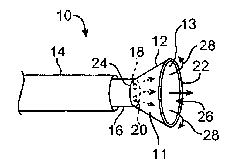
[0056]A tissue-imaging and manipulation apparatus described below is able to provide real-time images in vivo of tissue regions within a body lumen such as a heart, which is filled with blood flowing dynamically therethrough and is also able to provide intravascular tools and instruments for performing various procedures upon the imaged tissue regions. Such an apparatus may be utilized for many procedures, e.g., facilitating transseptal access to the left atrium, cannulating the coronary sinus, diagnosis of valve regurgitation / stenosis, valvuloplasty, atrial appendage closure, arrhythmogenic focus ablation, among other procedures. Further examples of tissue visualization catheters which may be utilized are shown and described in further detail in U.S. patent application Ser. No. 11 / 259,498 filed Oct. 25, 2005, which has been incorporated hereinabove by reference in its entirety.

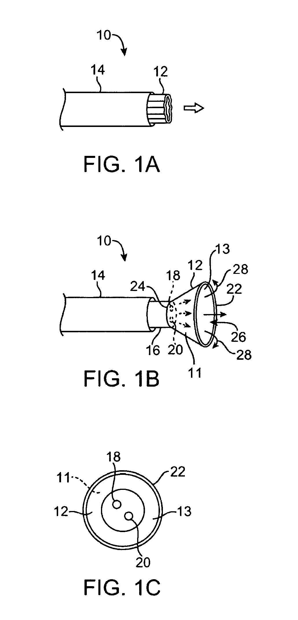
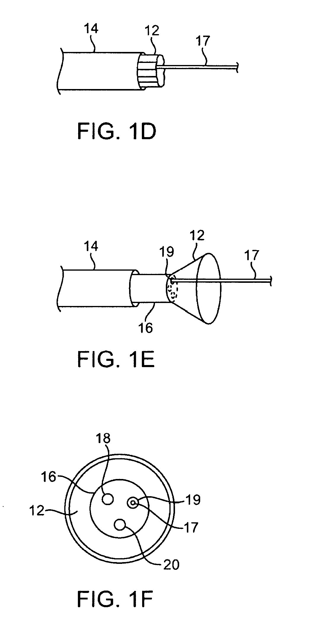
[0057]One variation of a tissue access and imaging apparatus is shown in the detail perspective views of F...


PUM


Abstract

Flow reduction hood systems are described which facilitate the visualization of tissue regions through a clear fluid. Such a system may include an imaging hood having one or more layers covering the distal opening and defines one or more apertures which control the infusion and controlled retention of the clearing fluid into the hood. In this manner, the amount of clearing fluid may be limited and the clarity of the imaging of the underlying tissue through the fluid within the hood may be maintained for relatively longer periods of time by inhibiting, delaying, or preventing the infusion of surrounding blood into the viewing field. The aperture size may be controlled to decrease or increase through selective inflation of the membrane or other mechanisms.

Description

CROSS-REFERENCE TO RELATED APPLICATIONS[0001]This application claims the benefit of priority to U.S. Prov. Pat. App. 60 / 888,242 filed Feb. 5, 2007, which is incorporated herein by reference in its entirety.FIELD OF THE INVENTION[0002]The present invention relates generally to medical devices used for accessing, visualizing, and / or treating regions of tissue within a body. More particularly, the present invention relates to flow reduction hood systems for accessing, visualizing, and / or treating tissue regions with devices that are configured to facilitate visualization of the tissue.BACKGROUND OF THE INVENTION[0003]Conventional devices for accessing and visualizing interior regions of a body lumen are known. For example, ultrasound devices have been used to produce images from within a body in vivo. Ultrasound has been used both with and without contrast agents, which typically enhance ultrasound-derived images.[0004]Other conventional methods have utilized catheters or probes having...

Claims


Application Information

Patent Timeline
IPC IPC(8): A61B6/00
CPCA61B1/0008A61B18/18A61B1/015A61B1/3137A61B6/503A61B1/00089A61B1/00165A61B1/018A61B1/05A61B1/051A61B1/12A61B1/32A61B5/6851A61B17/29A61B18/00A61B1/00147A61B1/00148
Inventor SAADAT, VAHIDTAM, EDMUNDROTHE, CHRIS A.MILLER, DAVIDPEH, RUEY-FENG
Owner INTUITIVE SURGICAL OPERATIONS INC
Why Eureka
Try Eureka