
Use Of Heat-Activated Adhesive For Manufacture And A Device So Manufactured

a technology of heat-activated adhesives and manufacturing processes, which is applied in the direction of printed circuit dielectrics, organic conductors, conductive materials, etc., can solve the problems of high sensitivity to the roughness of the substrate surface, difficult handling in an automated process, and high cost of tapes

Inactive Publication Date: 2008-08-14
CYPAK
View PDF10 Cites 116 Cited by
  • Summary
  • Abstract
  • Description
  • Claims
  • Application Information

AI Technical Summary

Benefits of technology

[0012]Another objective is to have an intelligent device comprising an electronic module and printed conductive traces on a flexible substrate, which device has an increased resistance to cracking and degradation of printed electronic devices.
[0053]It is preferred that the conductive traces have been printed before printing of the adhesive. After drying the adhesive can be activated at any time. A normal process involves a heat-sealing procedure (first activation) between two adhesive-coated paperboards or between an adhesive-coated and a paperboard without adhesive. After this the adhesive could be activated again (second step) when mounting any additional part (electronic module, electronic assembly, blister or lid). Such multiple activation processes clearly makes the re-activation property useful.

Problems solved by technology

Critical issues for producing intelligent disposable devices such as packages and disposable questionnaires are the attachment of the electronic module and the stability of the printed electronic devices like conductive traces, antennas etc on the package material.
Since the z-tapes are PSAs, they are sensitive to impurities in the environment like dust, which easily stick to the surfaces once the protective liners are removed.
They are difficult to handle in an automated process because of the removal of the release liner before attachment to a substrate.
The conductive agents in the z-tapes are usually metal particles with a highly defined diameter, making the tapes expensive and the sensitivity to the roughness of the substrate surface high.
Paperboard is a flexible material, but if wrinkles and creased or bent many times, the surface is likely to be damaged.
If a surface is damaged, the overlying print will be damaged as well.
The cracks at the surface are often seen as microscopic cracks in the printed conductive devices.
This is a serious threat to devices made of flexible materials with printed conductive traces or other devices on.
This leads to several problems.
One is the difficulty of handling tapes in an extra step in the production.
Another is that cracks are expected to appear in creasing, but also other areas could be susceptible and it would be a mayor effort that would imply several application steps to put supportive tape over the whole surface of a packaging.
This, however, involves many chemicals and materials that are dangerous and harm the environment.
Also, soldering is disadvantageous in flexible applications, since the soldering joint is stiff.
This is an expensive material making it hard to justify for use in the low-cost applications of disposable packages.
Other materials, such as polyesters, are not that resistant to heat, making it difficult or impossible to solder components to them.

Method used


Image

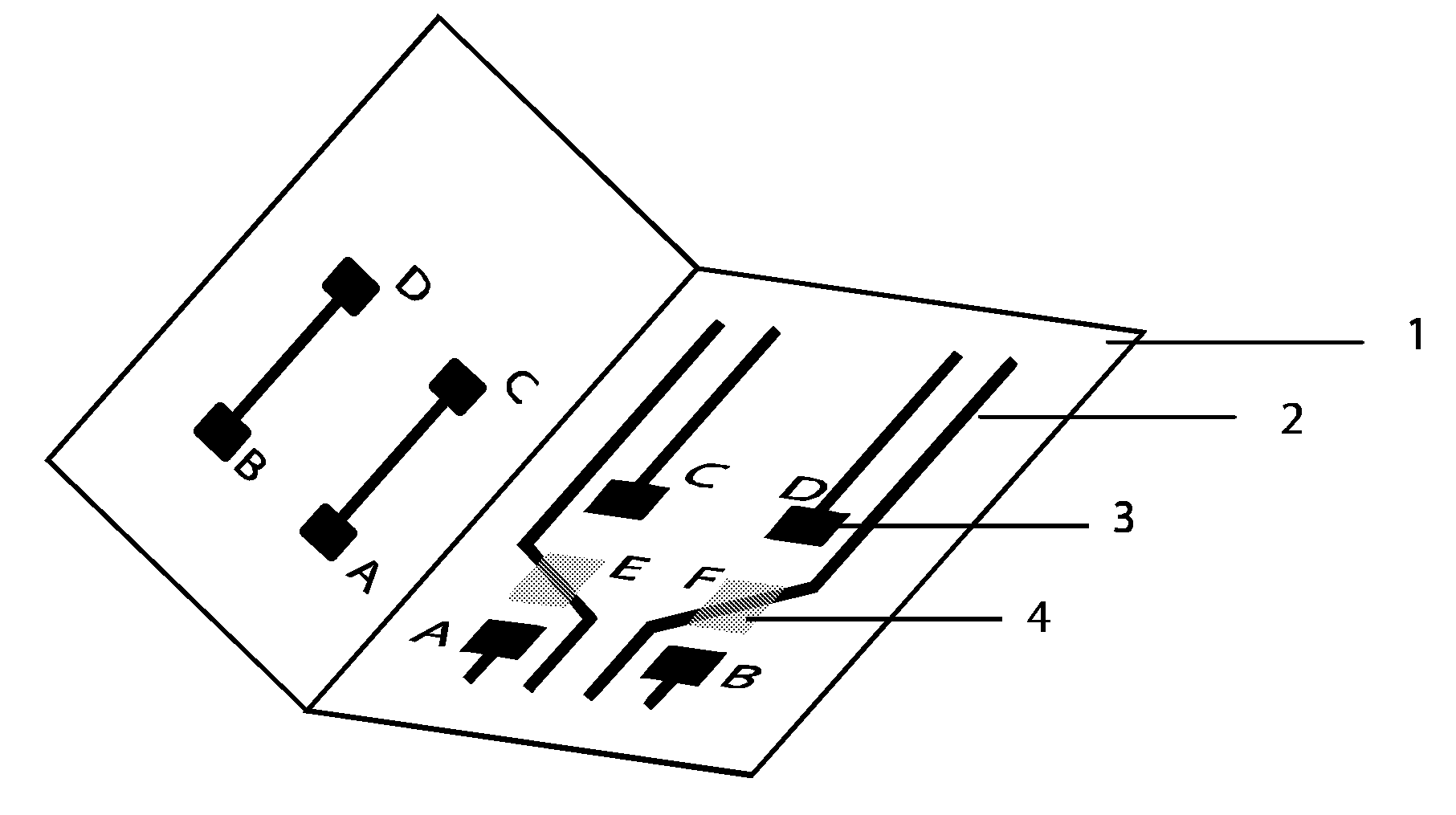
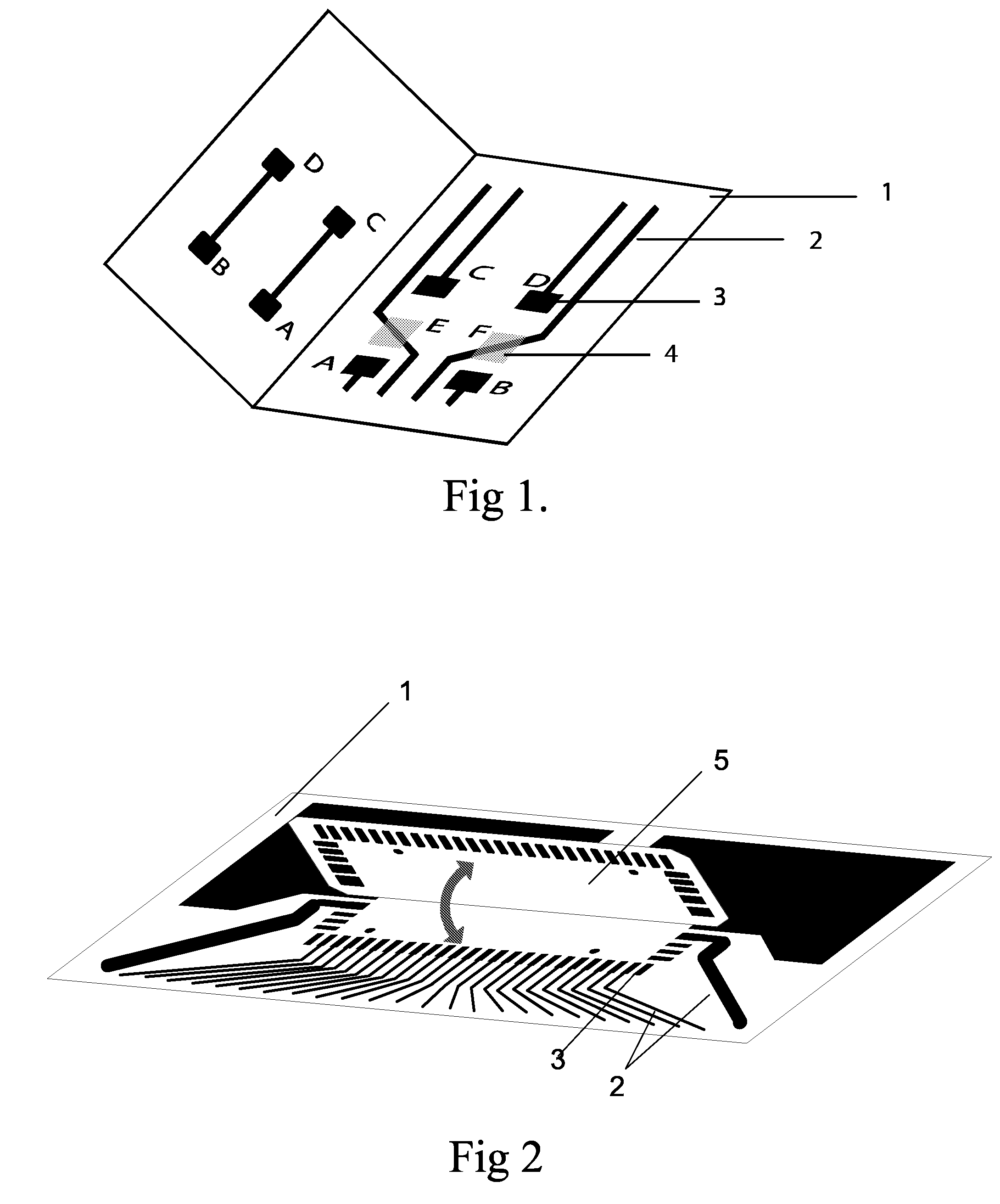
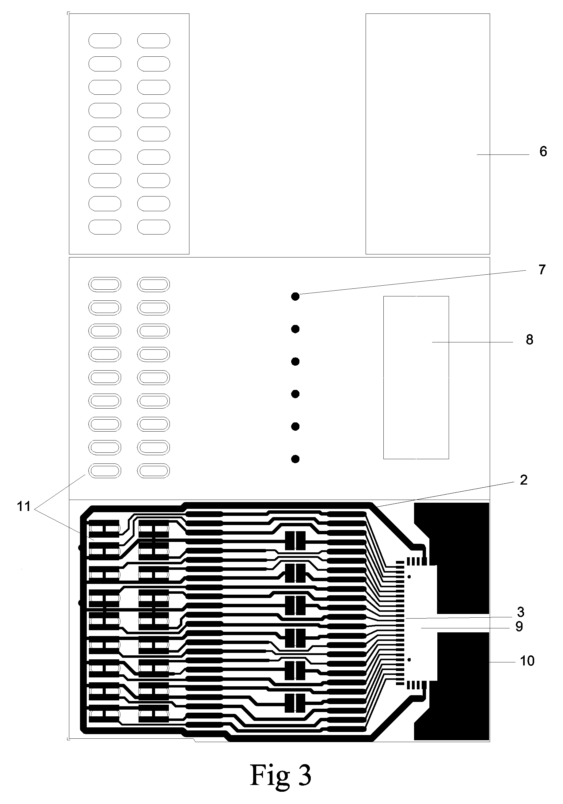
  • Use Of Heat-Activated Adhesive For Manufacture And A Device So Manufactured
  • Use Of Heat-Activated Adhesive For Manufacture And A Device So Manufactured
  • Use Of Heat-Activated Adhesive For Manufacture And A Device So Manufactured

Examples


example 1

Step 1

[0071]A water-based thermoplastic Ethylene Acrylic Acid (EAA) emulsion (35% dry weight) (Trade name: MichemPrime 4983 RHSA) is mixed with 3% (based on the dry weight) carbon black of electrical grade and mixed to homogeneity. The viscosity of the mixture is increased by adding 2% (based on wet weight) of an alkali swell able emulsion, ASE (trade name: Viscalex HV30).

Step 2

[0072]The formulated adhesive is screen printed on the uncoated side of the paperboard. The whole surface is covered, with exception for the printed buttons. A 60 mesh silk screen is used. After air-drying in controlled humidity the paperboard is embossed and die-cut. Before heat activation of the adhesive additional lids are removed so that the area where the electronic module is to be mounted remains open. These areas are covered with liners to avoid undesired adhesion during the activation. The activation temperature is 120 C for 20 seconds. After cooling the laminate is creased according to material spec...

example 2

[0075]Mounting of an electrical component to a plastic film can be done following the below steps.

Step 1

[0076]A water-based thermoplastic aliphatic polyurethane emulsion (45% dry weight) (Trade name: Kiwotherm D120) is mixed with 15% (based on the dry weight) silver coated nickel spheres and mixed to homogeneity.

[0077]FIG. 4 shows that a polyester (Poly EthyleneNaphthalate, PEN) film (1) with a metallized pattern (14) of gold coated copper is coated with a dielectric on selected areas (12) to avoid short-circuitry.

[0078]Step 2

[0079]The polyester film is bar-coated with the adhesive to a resulting thickness of 15 μm after drying.

Step 3

[0080]A battery is placed on the battery pad (13) on the polyester film (1) and a stamp activates the adhesive and seals the battery at a temperature of 120 C for 5 seconds. The polyester film (21) is folded and the back of the battery is sealed the same way so that the battery is enclosed in the film, see FIG. 5.

example 3

[0081]Fabrication of an electrical assembly

Step 1

[0082]A water-based thermoplastic aliphatic polyurethane emulsion (45% dry weight) (Trade name: Kiwotherm D120) is mixed with 15% (based on the dry weight) silver coated nickel spheres and mixed to homogeneity.

[0083]A polyester (Poly EthyleneNaphthalate, PEN) film with a metallized pattern of gold coated copper (see FIG. 4) is coated with a dielectric on selected areas to avoid short-circuitry.

Step 2

[0084]The polyester film is bar-coated with the adhesive to a resulting thickness of 15 μm after drying.

Step 3

[0085]A battery is placed on the battery pad on the polyester film and a stamp activates the adhesive and seals the battery at a temperature of 140 C for 2 seconds. The polyester film is folded and the back of the battery is sealed the same way so that the battery is enclosed in the film.

[0086]A piezo-element (buzzer) is placed on the buzzer pad on the polyester film and a stamp activates the adhesive and seals the buzzer at a tem...


PUM

PropertyMeasurementUnit
Fractionaaaaaaaaaa
Electric chargeaaaaaaaaaa
Concentrationaaaaaaaaaa

Abstract

The invention is based on use of a heat-activated adhesive for manufacturing of intelligent devices comprising printed conductive electronics on a flexible substrate, where the adhesive is an anisotropic electrically conductive adhesive and is applied to the substrate as a thin film which can be used for electrical connections and for providing mechanical stability to the printed conductive electronics.

Description

TECHNICAL FIELD[0001]The invention relates to use of heat-activated adhesive for manufacturing of intelligent devices comprising a flexible substrate with electronic components and conductive traces. The devices can be in the form of a card or a keypad or a package having one or more creasing.BACKGROUND OF THE INVENTION[0002]Intelligent packaging or intelligent devices has a broad definition, ranging from RFID tags mounted on paper to using PSA-tape to complex assemblies of electronic modules connected to printed conductive traces and antennas via electronic interconnections.[0003]Critical issues for producing intelligent disposable devices such as packages and disposable questionnaires are the attachment of the electronic module and the stability of the printed electronic devices like conductive traces, antennas etc on the package material. The attachment of the electronic module is normally done using an anisotropic conductive tape, z-tape, which provides adhesion and electric int...

Claims


Application Information

Patent Timeline
IPC IPC(8): C09J9/02
CPCC09J9/02H01R4/04H05K1/0275H05K3/245H05K3/323H05K2201/055H05K2201/0129H05K2203/0759H05K2203/1105H05K3/4685H05K3/361
Inventor EHRENSVARD, JAKOBERIKSSON, LEIF HENRIKLINDMAN, VILHELM
Owner CYPAK
Learn More