Electrode for electrolysis and electrolysis unit

a technology of electrolysis and electrolysis unit, which is applied in the direction of electrolysis components, electrolysis coatings, multiple component coatings, etc., can solve the problems of high cost of the device itself, ozone water having a desired concentration is difficult to efficiently form, and the device is liable to become complicated, so as to achieve the effect of reducing production cost, increasing ozone forming efficiency, and increasing energy level

Inactive Publication Date: 2008-09-11
SANYO ELECTRIC CO LTD
View PDF6 Cites 1 Cited by
  • Summary
  • Abstract
  • Description
  • Claims
  • Application Information

AI Technical Summary

Benefits of technology

[0021]Therefore, the electrons move with a higher energy level, whereby an ozone forming efficiency for causing the ozone forming reaction can be raised.
[0022]According to the invention of the fourth aspect, in the above inventions, the insulator is aluminum oxide, so that the electrode for electrolysis according to the above inventions can be made of a comparatively inexpensive material, and production cost can be reduced. Moreover, any toxic substance such as lead dioxide is not used, whereby an environmental load can be reduced.
[0023]According to the invention of the fifth aspect, in the above inventions, the thickness of the surface layer is in a range of 20 nm or more to 2000 nm or less, so that the surface layer can be made of a thin film, and the electrons can move in the electrode via impurities of the surface layer or Fowler-Nordheim tunneling. Therefore, owing to an electrode reaction in the anode, the empty level around the bottom of the conduction band at the energy level higher than Fermi level as much as about the half of the band gap can receive the electrons from the electrolyte, and the movement of the electrons is caused with the higher energy level, whereby the electrolysis can be performed with the low current density, and ozone can efficiently be formed.
[0024]According to the invention of the sixth aspect, in the above inventions, the substrate is provided with the intermediate layer positioned on the inner side of the surface layer and formed of the metal which is not easily oxidized on the surface of the substrate. Therefore, the electrode reaction can be caused with the high energy level in the surface of the surface layer. In consequence, ozone can efficiently be formed with a lower current density.
[0025]In particularly, according to such inventions, the intermediate layer is formed of the metal which is not easily oxidized on the surface of the substrate. Therefore, when the electrolysis is performed with the electrode, it is possible to avoid a disadvantage that the substrate surface is oxidized and non-conducted. In consequence, durability of the electrode can be improved. As compared with the whole substrate is made of the material constituting the intermediate layer, the production cost can be reduced. Even in such a case, ozone can similarly efficiently be formed.
[0026]In the electrolysis unit according to the invention of the seventh aspect, the anode having the water permeability is constituted of the electrode for electrolysis according to the above inventions, and the anode and the cathode having the water permeability are arranged on both the surfaces of the cation exchange film. Therefore, protons move in the cation exchange film, whereby even when the electrolytic solution is pure water, ozone can efficiently be formed.

Problems solved by technology

However, in the above-mentioned ozone water forming method for generating the ozone gas by the ultraviolet lamp or the discharge system described above to dissolve this ozone gas in the water, the ozone gas forming device, an operation for dissolving the ozone gas in the water and the like are required, so that the device is liable to become complicated.
The method is a method for dissolving the formed ozone gas in the water, and hence it has a problem that it is difficult to efficiently form the ozone water having a desired concentration.
However, in the method disclosed in Patent Document 3 described above, diamond is used as an electrode substance, and hence there is a problem that cost of the device itself soars.
However, the element as the electrode for forming ozone has a low ozone forming efficiency, and it is difficult to efficiently form the ozone water by an electrolysis process.
This raises a problem that very high energy is consumed.
Furthermore, platinum is expensive.
When lead dioxide is used instead of platinum, there is a problem of toxicity.

Method used


Image

  • Electrode for electrolysis and electrolysis unit
  • Electrode for electrolysis and electrolysis unit
  • Electrode for electrolysis and electrolysis unit

Examples


example 1

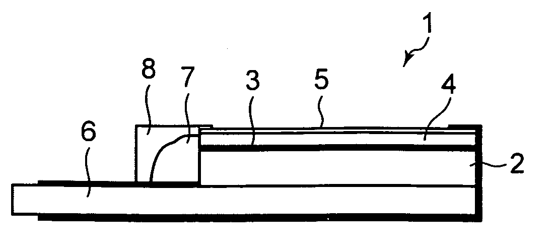
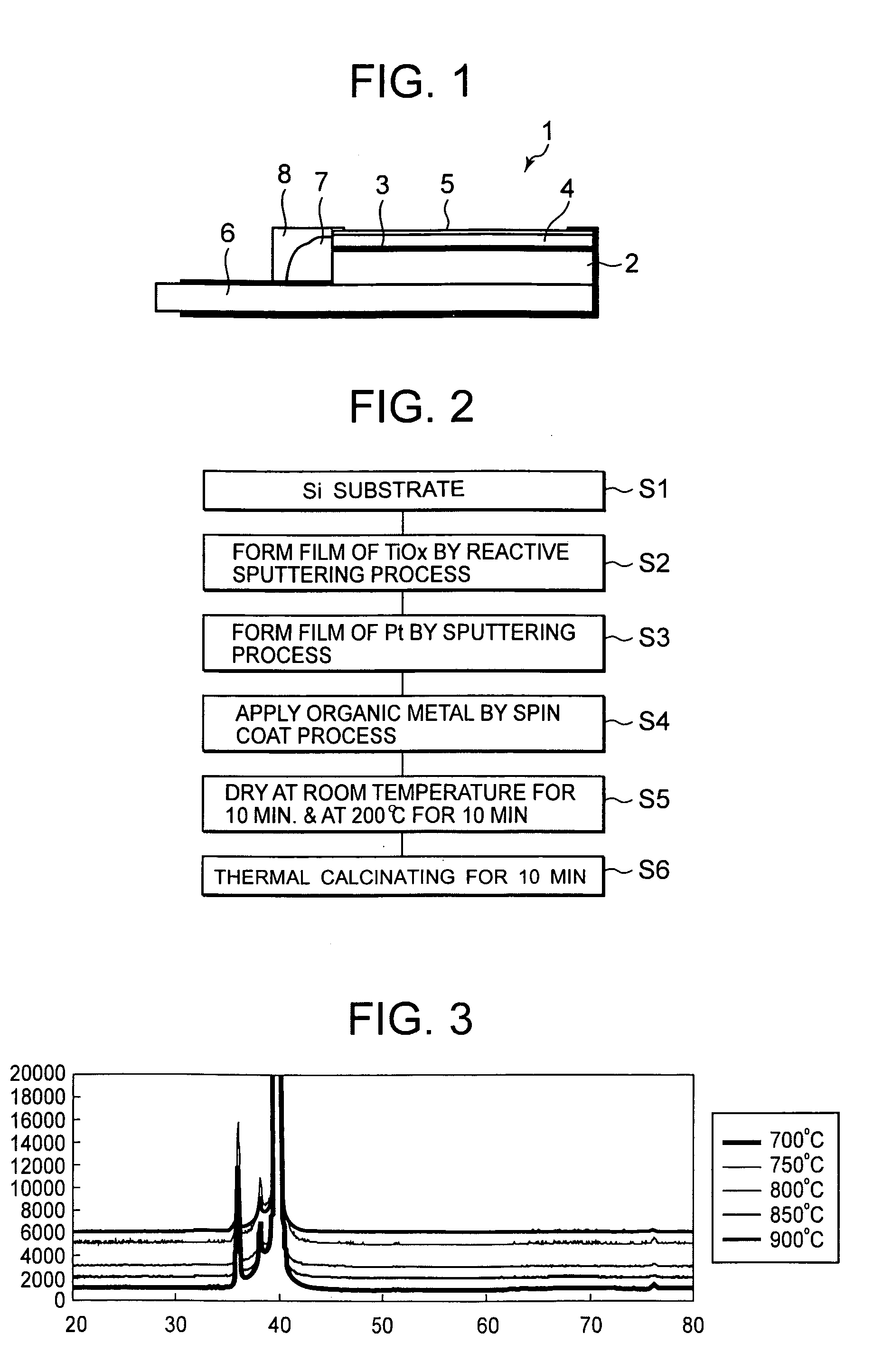
[0048]Next, a manufacturing method of an electrode 1 for electrolysis according to Example 1 of the present invention will be described with reference to a flow chart of FIG. 2. First, silicon (Si) constituting a substrate 2 is pretreated in step S1. Here, it is preferable that phosphorous (P), boron (B) and the like are introduced as impurities into Si to improve the conductivity. Si having a very flat surface is used. It is to be noted that in the present example, Si is used as the substrate 2, but a conductive material may be used.

[0049]In the pretreatment, the substrate 2 of Si is treated with 5% of hydrofluoric acid to remove a native oxide film formed on the surface of the substrate 2. In consequence, the surface of the substrate 2 is further flattened. It is to be noted that the pretreatment does not have to be performed. Afterward, the surface of the substrate 2 is rinsed with pure water, and then in step S2, the substrate is introduced into a chamber of an existing sputteri...

example 2

[0083]Next, a manufacturing method of an electrode 21 for electrolysis according to Example 2 of the present invention will be described with reference to a flow chart of FIG. 6. It is to be noted that FIG. 7 is a schematic constitution diagram of the electrode 21 for electrolysis obtained by the example. First, in step S11, Si constituting a substrate 22 is pretreated in the same manner as in the above example. A material of the substrate 22 is similar to that of the above example, so that description thereof is omitted. Subsequently, in step S12, the substrate is introduced into a chamber of an existing sputtering device to form a film.

[0084]In the step S12, a close contact layer 23 for improving a close contact property of an intermediate layer 24 is formed on the surface of the substrate 22 as described above. The close contact layer 23 is formed on the substrate 22 by a reactive sputtering process in the same manner as in the above example. The close contact layer 23 is made of...

example 3

[0101]Next, an electrode for electrolysis according to Example 3 of the present invention will be described. It is to be noted that a manufacturing method of an electrode 31 for electrolysis obtained according to such an example is similar to that shown in the flow chart of FIG. 2 in Example 1, and a schematic constitution diagram is substantially similar to FIG. 1, so that detailed description of the manufacturing method is omitted.

[0102]That is, in the electrode for electrolysis according to the example, a close contact layer 3 of titanium oxide is formed on the surface of Si constituting a substrate by a sputtering process as described above, and an intermediate layer 4 of platinum is formed on the surface of the close contact layer 3 by the sputtering process.

[0103]Subsequently, a surface layer 5 is formed on the surface of a substrate 2 provided with the intermediate layer 4. In such an example, the surface layer 5 is formed by a spin coat process, so that the surface of the su...


PUM

PropertyMeasurementUnit
thicknessaaaaaaaaaa
current densityaaaaaaaaaa
thicknessaaaaaaaaaa

Abstract

There are disclosed an electrode for electrolysis capable of efficiently forming ozone by electrolysis of an electrolytic solution (e.g., water) at ordinary temperature with a low current density, and an electrolysis unit using the electrode. The electrode for electrolysis includes a substrate and a surface layer formed on the surface of the substrate, and the surface layer is made of an amorphous insulator, for example, a thin film of amorphous tantalum oxide, amorphous tungsten oxide or amorphous aluminum oxide.

Description

BACKGROUND OF THE INVENTION[0001]The present invention relates to an electrode for electrolysis for use in an industrial or household electrolysis process.[0002]In general, ozone is a substance having a very strong oxidizing power, and it is expected that water in which ozone is dissolved, so-called ozone water is applied to a broad range of cleaning sterilization treatment of water and sewage, food and the like, and a cleaning treatment of a semiconductor device manufacturing process. As methods for forming the ozone water, there are known a method for dissolving, in water, ozone formed by irradiation with an ultraviolet ray or electric discharge, a method for forming ozone in water by electrolysis of the water, and the like.[0003]In Japanese Patent Application Laid-Open No. 11-77060 (Patent Document 1), an ozone water forming device is disclosed which includes ozone forming means for forming an ozone gas with an ultraviolet lamp and a tank to store water, whereby the formed ozone ...

Claims


Application Information

Patent Timeline
Patent Type & Authority Applications(United States)
IPC IPC(8): C25B9/00C25B11/04
CPCC25B11/0484C25B1/13C25B11/093
Inventor KITSUKA, KENTAKANEDA, KAZUHIROIKEMATSU, MINEOKAWATA, KATSURA
Owner SANYO ELECTRIC CO LTD
Why Eureka
Try Eureka