Photoelectric sensor, information recording method, and information recording system

a technology of information recording and photoelectric sensor, which is applied in the field of information recording system, can solve the problems of no image can be recorded again, no effective recording of information, and inability to record an image of good quality on liquid crystal recording medium

Inactive Publication Date: 2008-09-25
DAI NIPPON PRINTING CO LTD
View PDF0 Cites 9 Cited by
  • Summary
  • Abstract
  • Description
  • Claims
  • Application Information

AI Technical Summary

Benefits of technology

[0052]According to a still further aspect of the present invention, there is provided an information recording system constructed from a one-piece type medium comprising a photoelectric sensor having a photoconductive layer stacked on a transparent electrode, an information recording medium having an information recording layer stacked on an electrode and an upper electrode, said photoelectric sensor being opposed to said information recording medium on the optical axis with a gap located therebetween, or said photoelectric sensor being stacked on said information recording medium with or without a diel

Problems solved by technology

Therefore, unless the conductivity difference between the exposed and unexposed portions shown in FIG. 1 reaches a certain value, it is then impossible to record an image of good quality on the liquid crystal recording medium.
At too low an applied voltage, however, no image can again be recorded because the voltage of the liquid crystal recording medium at the unexposed portion does not reach the threshold voltage.
As described above, it is required that when information is recorded, the application of voltage be finished within a prescribed time; that is, no effective recording of information is achieved even when the application of voltage is continued after an elapse of that time.
However, such a photoelectric sensor cannot be used to record information by a prior art recording method wherein the application of voltage is started at the same time as exposure.
With such

Method used


Image

  • Photoelectric sensor, information recording method, and information recording system
  • Photoelectric sensor, information recording method, and information recording system
  • Photoelectric sensor, information recording method, and information recording system

Examples


example 1

[0160]An ITO film of 100 nm in thickness was sputtered on a well washed glass substrate of 1.1 mm in thickness to obtain an electrode layer.

[0161]Then, 3 parts by weight of a bisazo pigment of the structure given below, 0.75 parts by weight of a vinyl chloride-vinyl acetate copolymer, 0.25 parts by weight of polyvinyl acetate, 98 parts by weight of 1,4-dioxane and 98 parts by weight of cyclohexanone were mixed together and dispersed in each other in a paint shaker for 6 hours to prepare a coating solution. The coating solution was spin-coated on the above electrode layer at 1,400 rpm for 0.4 seconds, and then dried at 100° C. for 1 hour to obtain a carrier generation layer of 300 nm in thickness.

[0162]A coating solution obtained by mixing together 1 part by weight of a carrier transport substance or a compound of the following structure, 4 parts by weight of polystyrene resin, 22 parts by weight of 1,1,2-trichloromethane and 14 parts by weight of dichloromethane was spin-coated on t...

example 2

[0168]The characteristics of the photoelectric sensor were measured following Example 1 with the exception that voltage was applied thereto as follows.

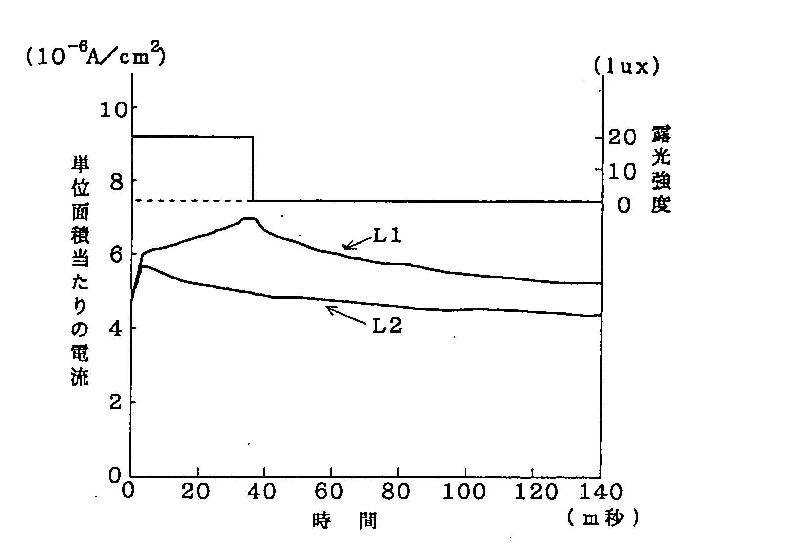
[0169]The photoelectric sensor was exposed to 20-lux light for 33 milliseconds at a constant applied voltage of 200 volts, and at a rectangular wave form of applied voltage of 200 volts. The resulting current data are shown in FIG. 16. The application of the rectangular wave to the sensor was carried out every 50 msec.

[0170]The currents obtained at the constant applied voltage are shown by broken lines, and the currents obtained at the rectangular wave form of applied voltage by solid lines.

[0171]At no applied voltage no current flows. Either at the constant applied voltage of 200 volts or at the rectangular wave or pulse form of applied voltage of 200 volts, however, the currents have an almost equal value. Even in the cycle in which the finish of the application of voltage is followed by resuming the application of voltage, the obta...

example 3

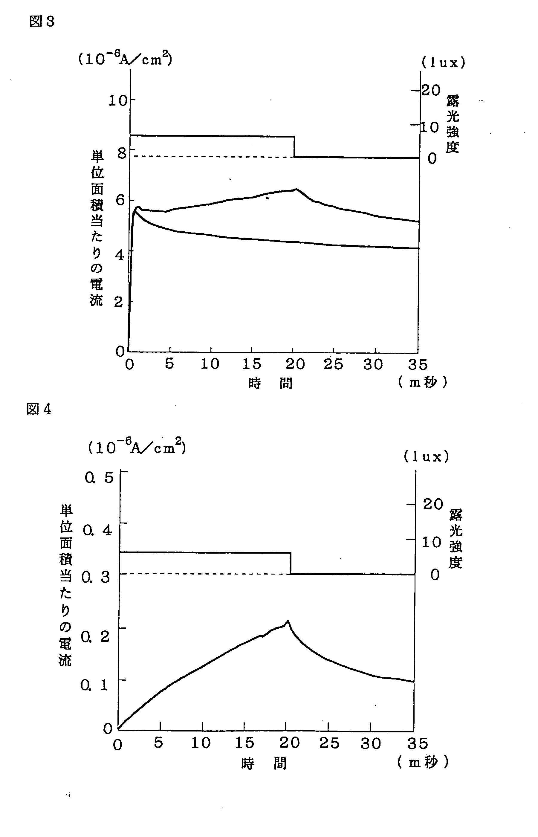
[0174]The photoelectric sensor was exposed to 12-lux light for an exposure time of 500 msec. In FIG. 17, the current obtained when a constant voltage of 200 volts was continuously applied thereto as in Example 2 is shown by a broken line, and the current obtained when the application of a rectangular wave form of voltage thereto was continued for 50 msec., and then interrupted for 50 milliseconds by a solid line. As in Examples 1 and 2, the photo-induced current continues to increase during exposure in the state where a constant voltage is applied to the sensor. When the rectangular wave voltage in a pulse form is applied to the sensor, however, the photo-induced current is found to increase during exposure even at an applied voltage of 0 volt.


PUM

PropertyMeasurementUnit
Timeaaaaaaaaaa
Current densityaaaaaaaaaa
Electric fieldaaaaaaaaaa

Abstract

The present invention relates to an information recording system comprising an information recording medium and a photoelectric sensor capable of recording light information on the information recording medium in the form of visible information or electrostatic information, and to an information recording method wherein light information is recorded on an information recording medium utilizing an photoelectric sensor.

Description

BACKGROUND OF THE INVENTION[0001]The present invention relates to an information recording system comprising an information recording medium and a photoelectric sensor capable of recording light information on the information recording medium in the form of visible information or electrostatic information. More particularly, the present invention relates to a photo-electric sensor including a photoconductive layer that enables the ability of an information recording medium to record information to be noticeably amplified as well as an w information recording method and system that uses this photoelectric sensor.[0002]There has so far been an information recording and reproducing method in which a photoelectric sensor having a photoconductive layer provided with an electrode on the front side is opposed, on the optical axis, to an information recording medium having an electric charge retaining layer provided with an electrode on the rear side thereof, and the sensor is exposed to li...

Claims


Application Information

Patent Timeline
IPC IPC(8): G02F1/135G01J1/02B41M5/26G02F1/13G03G5/047G11B7/00G11B7/0045G11B11/00G11B11/08
CPCG01J1/42G02F1/1354G02F2001/13775G03G5/0542G03G5/0696G03G5/0564G03G5/0614G03G5/0622G03G5/0675G03G5/056G03G5/06147G03G5/061473G02F1/13775
Inventor OKABE, MASATO
Owner DAI NIPPON PRINTING CO LTD
Why Eureka
Try Eureka