Gas Diffusion Electrodes, Membrane-Electrode Assemblies and Method for the Production Thereof

a technology of gas diffusion electrodes and membrane electrodes, which is applied in the manufacture of cables/conductor parts, electrical equipment, fuel cells, etc., can solve the problems of cumbersome scale up, difficult control of exchange membranes, and common physical and chemical vapor deposition techniques (pvd or cvd), and achieves a surprising enhancement of catalyst utilization factor, uniform local permeability of coatings, and increased useful catalytic surface effects

Inactive Publication Date: 2008-10-16
BASF FUEL CELL
View PDF11 Cites 2 Cited by
  • Summary
  • Abstract
  • Description
  • Claims
  • Application Information

AI Technical Summary

Benefits of technology

[0016]It is an another object of the invention to provide a gas diffusion electrode obtained by direct metallization of a gas diffusion medium with low platinum loading characterized by very high performances, especially at high current density, preferably free of ionomeric fluorocarbon components, and a membrane-electrode assembly incorporating the same.
[0018]Under one aspect, the gas diffusion electrode of the invention consists of a gas diffusion medium, free of ionomeric components, provided with a patterned noble metal coating by means of a dual IBAD deposition. It has been surprisingly found that the performances of the gas diffusion electrode can be greatly enhanced by depositing the metal catalyst coating according to well-chosen patterns, leaving a substantial portion of the gas diffusion medium uncovered (and thus uncatalysed). In other words, provided an appropriate geometry is chosen for the catalyst deposition, the loss of catalytic activity in the uncatalysed zones results more than compensated by the enhanced permeability introduced by the discontinuity in the metal coating.
[0021]Surprisingly, the optimum geometrical parameters for the patterned noble metal coatings of the invention result in a quite coarse geometry, the best results being obtained when the main lattice parameter (which can be identified as the distance between the centers of two adjacent holes in the mask) is in the order of magnitude of a few tens of a millimeter to a few millimeters. In a preferred embodiment, the distance between the centers in adjacent couples of holes is between 0.02 and 0.5 cm. In a preferred embodiment, the method of the invention is preferably practiced making use of a patterned mask with an open ratio between 30 and 80% and in this context, the term open ratio indicates the ratio between the area corresponding to the holes and the total area of the mask, as known in the art. In a preferred embodiment, the patterned mask is implemented as a grid, in particular as a polygonal grid, for instance, comprised of equally spaced polygonal holes, so that the resulting metal coating consists of a pattern of equally spaced polygons. In a still more preferred embodiment, the polygonal grid consists of equally spaced polygons with a filled round center, so that the resulting metal coating consists of a pattern of equally spaced polygons with a round hole at their center. In this way, the catalyst utilization factor is surprisingly enhanced since there is a comparatively higher fraction of catalyst exposed at the edges, and the local permeability of the coating is more uniform.
[0022]The thickness of the pattern noble metal coating of the invention is preferably comprised between 5 and 250 nm and the corresponding loading between 0.01 and 0.3 cm2. A thickness toward the high end of this range is more advantageous compared to the analogous case of continuous (non-patterned) coating disclosed in the co-pending Provisional U.S. Patent Application Ser. No. 60 / 580,739 since in the present case, the coating grows as an array of three dimensional elements (prisms or cylinders or other shapes characterized by vertical walls, depending on the geometry of the mask), whose vertical walls are easily accessible to the gaseous reactants thereby increasing the useful catalytic surface.

Problems solved by technology

Nevertheless, the noble metal component is exploited to such a low extent in structures of this kind, that very high specific loadings are required (usually in the range of 0.3 to 1 mg / cm2 of platinum both for the anode and for the cathode side in commercially available products).
However, no means for direct metallization of membranes has proven effective and practical up to now.
High temperatures required by sputtering or ultra high vacuum deposition (UHV) are destined to impart consistent damages to the delicate ion-exchange membranes, and even the common physical and chemical vapor deposition techniques (PVD or CVD) have proven too difficult to control and cumbersome to scale up.
Since the handling of a large sized ion-exchange membrane in a continuous metallization process is not very easy, a further improvement of this technique has been disclosed in U.S. Pat. No. 6,673,127.
Firstly, although the performances of these electrodes can be high, they can be somewhat unpredictable since the reliability of this technique is affected by the characteristics of the ionomer film, which can vary according to the preparation conditions.
Moreover, also in the best cases, the utilization factor of the catalyst with liquid ionomer-embedded particles does never approach unity.
Besides solving the issue of lowering the platinum loading (or more generally the noble metal loading) in fuel cell electrodes, another problem which should be addressed is the low stability of fluorocarbon-based ionomeric components in membrane-electrode assemblies at certain process conditions.
In any case, none of these materials has proven suitable for being employed as a proton conducting material for the electrode interface according to the teaching of U.S. Pat. No. 4,876,115 and perfluorocarbon materials such as the aforementioned “Liquid Nafion” are always used.
However, some undesired limitations can be noticed with this type of electrode at higher current densities (around 1 A / cm2), as cell voltage tends to drop suddenly due to the onset of diffusive limitations.
Most likely, the diffusion rate of the gaseous reactants through the noble metal coating obtained by dual IBAD is not sufficient to sustain operation above a certain current density.

Method used


Image

  • Gas Diffusion Electrodes, Membrane-Electrode Assemblies and Method for the Production Thereof
  • Gas Diffusion Electrodes, Membrane-Electrode Assemblies and Method for the Production Thereof
  • Gas Diffusion Electrodes, Membrane-Electrode Assemblies and Method for the Production Thereof

Examples


Embodiment Construction

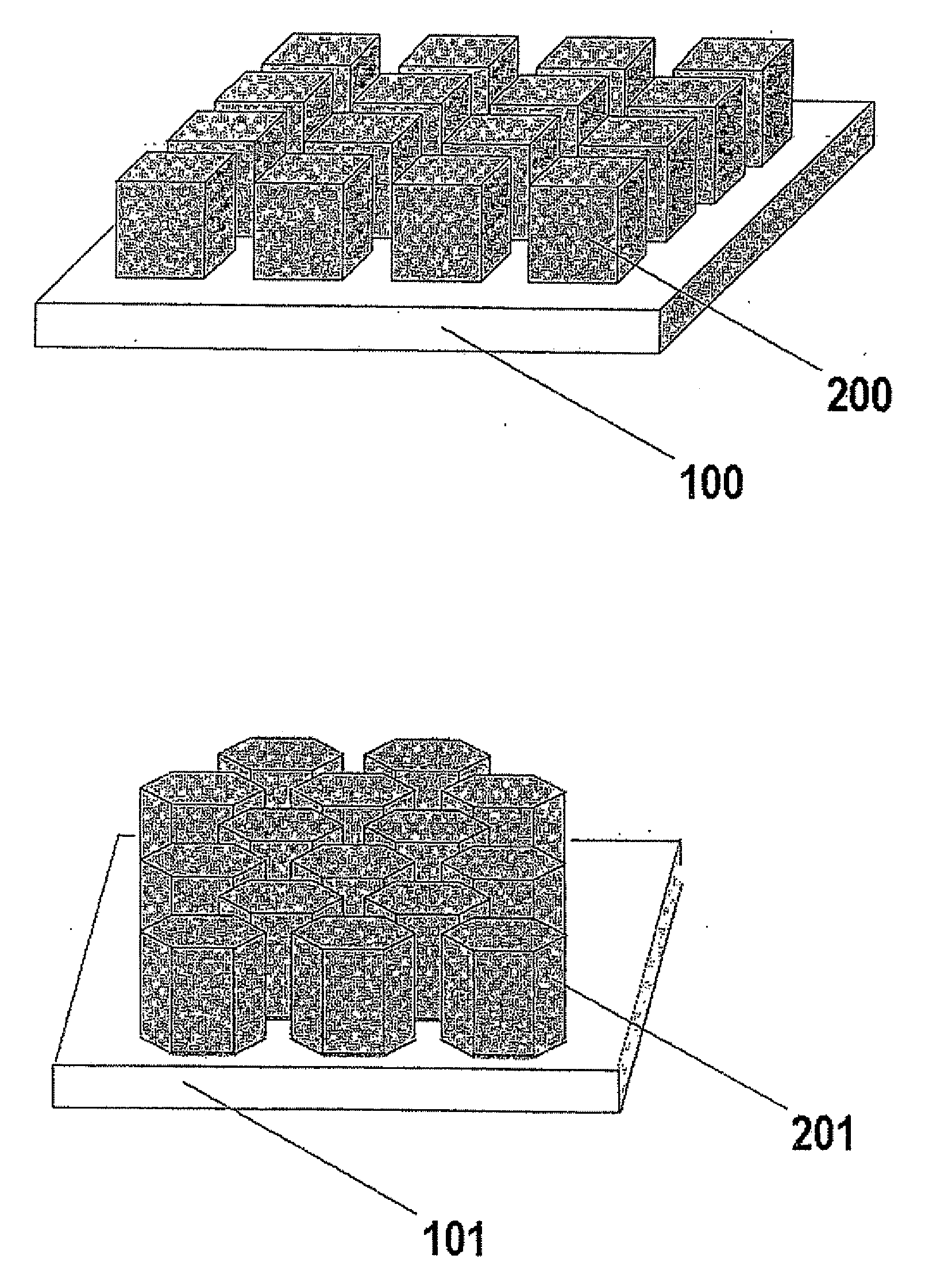
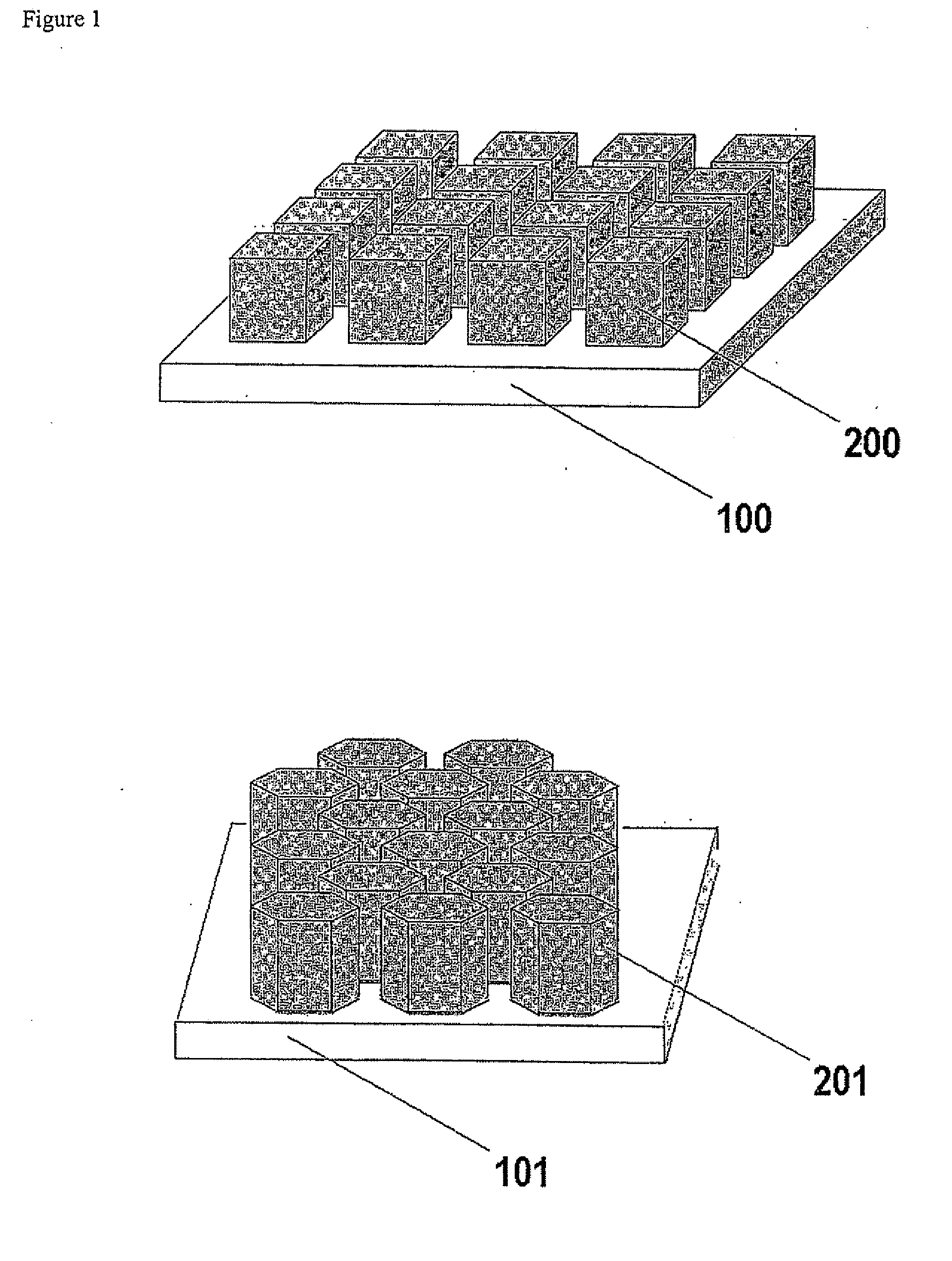
[0032]A series of gas diffusion electrodes was prepared according to the Example of the cited U.S. Provisional Patent Application Ser. No. 60 / 580,739, the difference being that a series of masks were interposed between the gas diffusion medium and the IBAD source to obtain patterned noble metal coatings. Platinum was selected as the noble metal to apply, as in the case of the cited application. A gas diffusion medium was selected consisting of a three-dimensional woven carbon cloth coated with a mixture of Shawinigan Acetylene Black carbon particles and PTFE, for a total thickness of 410 microns, a basis weight of 210 g / m2, a density of 0.54 g / cm3, an electrical resistivity of 525 mΩcm, an air permeability of 0.84 Gurley, a porosity of 25 microns with a mean pore size of 6 microns and an average smoothness of 5000 Gurley seconds. The gas diffusion medium so obtained was divided into equivalent pieces, each of which were subjected to dual IBAD deposition of platinum metal after overl...


PUM

PropertyMeasurementUnit
energyaaaaaaaaaa
distanceaaaaaaaaaa
distanceaaaaaaaaaa

Abstract

A method for forming a patterned noble metal coating on a gas diffusion medium substantially free of ionomeric components comprising subjecting an electrically conductive web with a patterned mask overlaid thereto to a first ion beam having an energy not higher than 500 eV, and to a second beam having an energy of at least 500 eV, containing the ions of at least one noble metal and a gas diffusion electrode.

Description

[0001]The application claims the benefit of U.S. provisional patent application Ser. No. 60 / 671,336 filed Apr. 14, 2005.FIELD OF THE INVENTION[0002]The invention relates to gas diffusion electrodes for use in fuel cells and other electrochemical applications, and to the relevant method of production.BACKGROUND OF THE INVENTION[0003]Proton exchange membrane fuel cells (PEMFC) are considered to be one of the most promising sources of clean electrical energy for the near future. PEMFC are electrochemical generators which produce direct electrical current from a gaseous fuel (typically hydrogen, pure or in admixture) and a gaseous oxidant, normally consisting of oxygen or air. The core component of the cell is the membrane-electrode assembly, consisting of an ion-exchange membrane, which is the solid electrolyte supporting the whole process and the physical separator of the anode and cathode cell compartments, bonded or otherwise coupled to gas diffusion electrodes. The gas diffusion el...

Claims


Application Information

Patent Timeline
Patent Type & Authority Applications(United States)
IPC IPC(8): H01M4/00H01B13/00
CPCH01M4/8807H01M4/8825H01M4/92Y10T29/49108H01M8/1002Y02E60/521H01M8/0245H01M8/1007Y02P70/50Y02E60/50H01M4/86H01M4/88H01M8/10C25B11/03
Inventor GULLA, ANDREAALLEN, ROBERT
Owner BASF FUEL CELL
Why Eureka
Try Eureka