

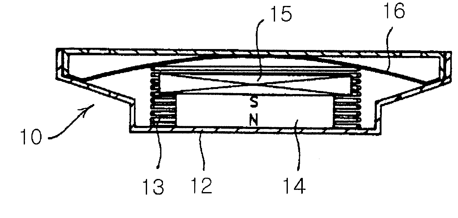
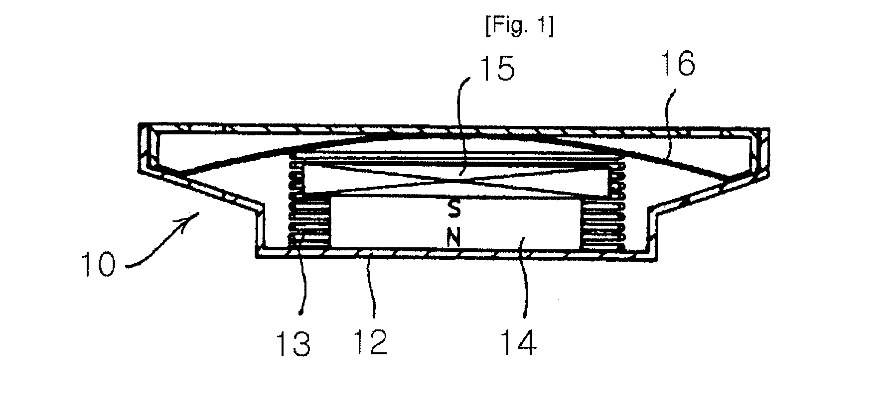
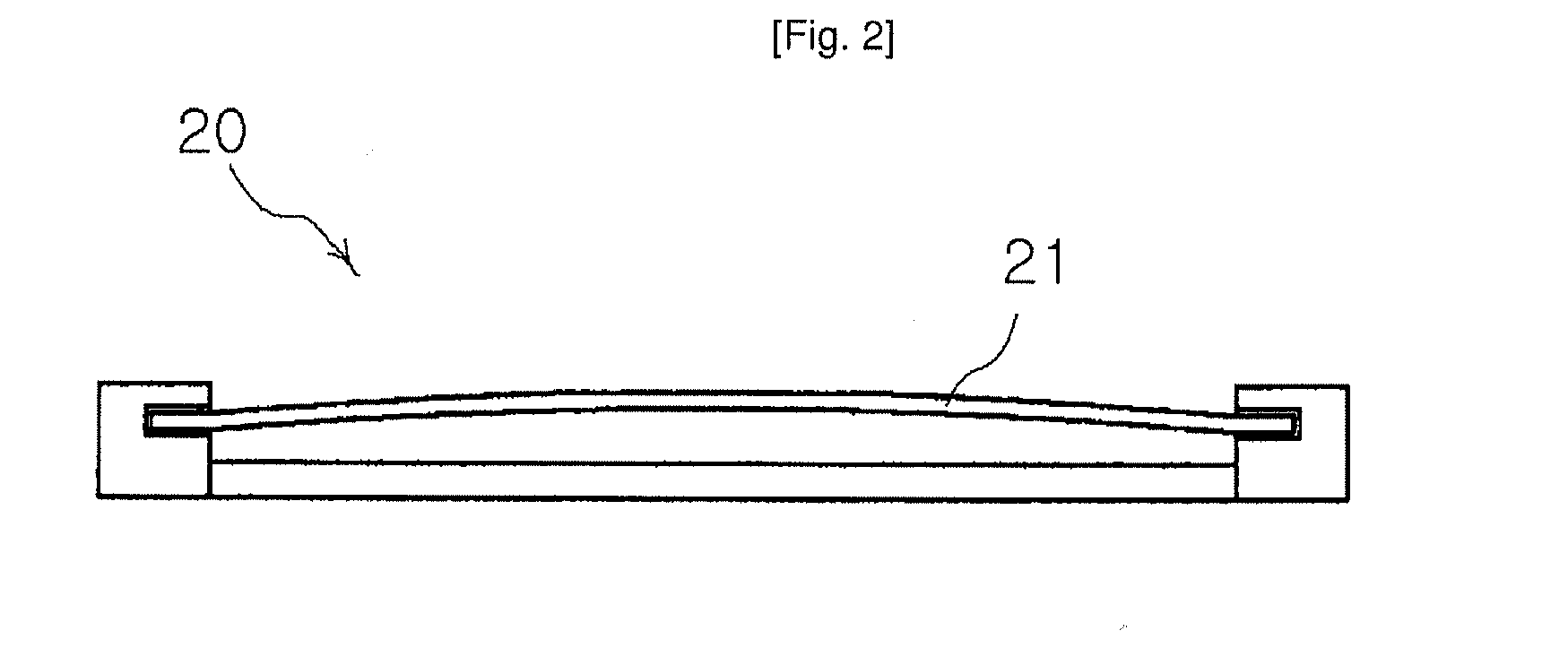
Acoustic Diaphragm and Speaker Having the Same
a diaphragm and acoustic technology, applied in the direction of transducer diaphragms, electromechanical transducers, instruments, etc., can solve the problems of high internal loss, low density, and high internal loss of diaphragms to achieve diaphragms. , to achieve the effect of excellent physical properties and superior sound quality
- Summary
- Abstract
- Description
- Claims
- Application Information
AI Technical Summary
Benefits of technology
Problems solved by technology
Method used
Image

Examples
example 1
[0069]An acoustic diaphragm was produced using polyvinylidene fluoride (PVDF) as an adhesive and carbon nanotubes as major materials. The carbon nanotubes used herein were single-walled carbon nanotubes (SWNTs) having an average diameter of 1 nm and a length of 1 μm. The weight ratio of the carbon nanotubes to the polyvinylidene fluoride was adjusted to 90:10.
[0070]First, 0.22 g of polyvinylidene fluoride as an adhesive was dissolved in 30 ml of ace tone as a solvent in an Erlenmeyer flask. 2 g of the carbon nanotubes was added to the adhesive solution and the mixture was homogeneously mixed using an ultrasonicator. For homogeneous mixing, stirring was carried out for about 30 minutes. After the stirring, the homogeneous mixture was poured into a mold having a diameter of 20 mm and a thickness of 1 mm. The mold was placed in an oven at the temperature of 80° C. and allowed to stand for about one day to evaporate the solvent and stabilize the carbon nanotubes. After the mold was cool...
example 2
[0071]Acoustic diaphragms were produced using carbon nanotubes and polyethylene. The polyethylene was used as an adhesive to bond the carbon nanotubes to each other and also used as another major material, thus achieving synergistic effects. The carbon nanotubes used herein were single-walled carbon nanotubes (SWNTs) having an average diameter of 1 nm and a length of 1 μm. The carbon nanotubes were used in an amount of 33% to 95% by weight, based on the weight of each of the final diaphragms. The polyethylene was used in an amount of 5% to 67% by weight, based on the weight of each of the final diaphragms.
[0072]30 ml of acetone as a solvent was put in Erlenmeyer flasks, and then 0.25 g, 1 g, 2 g and 3 g of the carbon nanotubes were added to the respective Erlenmeyer flasks. After the mixtures were homogeneously mixed using an ultrasonicator, 0.5 g, 0.5 g, 0.15 g and 0.1 g of polyethylene were slowly added dropwise thereto with violent stirring. For homogeneous mixing, the resulting ...
example 3
[0073]The procedure of Example 2 was repeated, except that a surfactant was further used to enhance the degree of dispersion of the carbon nanotubes without changing the conditions employed and the contents of the materials used in Example 2.
[0074]As the surfactant, polyoxyethylene-8-lauryl ether, CH3—(CH2)11(OCH2CH2)7OCH2 CH3 (hereinafter, referred to simply as “C12EO8”) was used. The surfactant was used in an amount of 5% to 60% by weight with respect to the weight of the carbon nanotubes used.
[0075]30 ml of acetone as a solvent was put in Erlenmeyer flasks, and then 0.3 g of C12EO8 was uniformly dissolved in the solvent. After 0.5 g, 1 g, 2 g and 3 g of the carbon nanotubes were added to the respective Erlenmeyer flasks, the mixtures were homogeneously mixed using an ultrasonicator. The following procedure was performed in the same manner as in Example 1 to produce acoustic diaphragms in which the surfactant was used to disperse the carbon nanotubes and the polymer.
[0076]The carb...
PUM
 Abstract
Description
Claims
Application Information