Catalyst, catalyst precursor, and catalyst carrier

a catalyst and precursor technology, applied in the direction of catalyst activation/preparation, metal/metal-oxide/metal-hydroxide catalysts, natural mineral layered products, etc., can solve the problems of too restrictive mass transfer limitations, complicated design of further improved catalyst particles, and inability to achieve the effect of achieving the trilobe shap

Inactive Publication Date: 2008-10-23
SHELL OIL CO
View PDF22 Cites 34 Cited by
  • Summary
  • Abstract
  • Description
  • Claims
  • Application Information

AI Technical Summary

Benefits of technology

[0026]In order to produce a catalyst, catalyst precursor, or catalyst carrier according to the present invention by an extrusion process, a paste comprising the carrier and optionally the active metal or precursor therefor and optionally the promoter, is fed from a hopper into an extruder. A number of dies at the end of the extruder each comprise a plurality of small apertures through which the paste is forced. The resulting extrudate is an elongated particle suitable for use in a fixed bed reactor for instance a multitubular reactor. Other methods to produce a catalyst, catalyst precursor, or catalyst carrier according to the present invention are, for example, pelletizing and pressure moulding.
[0027]Contrary to that which may be attempted by a skilled person, the inventors of the present invention have discovered a shape which has beneficial strength properties of the trilobe shape (TL) and diffusion limitation properties of the extended trilobe (Tx) shape but surprisingly have not chosen a shape which is a hybrid of these two shapes.
[0028]When comparing the prior art shapes with the current invention using the “inner ratio” and “outer ratio” terminology, the following remark can be made with regard to the TL shape. The basic trilobed shape (TL) has no central circle and no unoccupied circles and so the ratio of the diameter of the central circle to the diameter of the outer occupied circle (inner ratio) for the basic trilobe shape can be considered to be zero. Similarly the ratio of the unoccupied circle to occupied circle (outer ratio) is also zero for the TL shape.
[0029]The central circle of the cross-section of a catalyst, catalyst precursor, or catalyst carrier according to the present invention preferably has an exposed edge. This is in contrast to the extended trilobe shape Tx in which the central circle is in contact with the outer occupied circles and the interstitial areas. In one embodiment of the present invention, the central circle preferably has three exposed edges—typically each between two occupied outer circles.
[0030]Preferably the diameters of the three outer occupied circles differ less than 5% from each other, more preferably less than 2%. Most preferably the diameters of the three outer occupied circles are the same.
[0031]Preferably the nominal diameter of the extrudates is 0.5-6 mm, preferably 1-3 mm. The nominal diameter is the length from the furthest point on one outer occupied circle through the central circle centre and extending to a line drawn between the bottom of each of the remaining outer filled circles.

Problems solved by technology

However, providing a catalyst shape with a sufficient strength but with maximum surface area are somewhat conflicting requirements which complicates the design of further improved catalyst particles.
A trilobe catalyst with a ‘cloverleaf’ cross section shows a good mechanical strength but the mass transfer limitations are considered too restrictive.
Especially for Fisher Tropsch reactions and hydrocracking reactions the mass transfer limitations of such trilobe catalysts are too restrictive.
Catalyst particles according to WO 03 / 103833 show a relatively small amount of the unwanted mass transfer limitations but the shape has been found to suffer from poor strength, making handling outside the reactor difficult.

Method used


Image

  • Catalyst, catalyst precursor, and catalyst carrier
  • Catalyst, catalyst precursor, and catalyst carrier

Examples


example 1

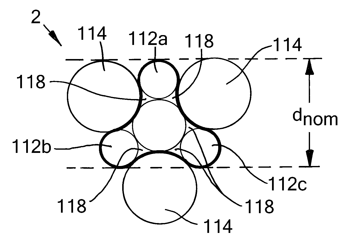
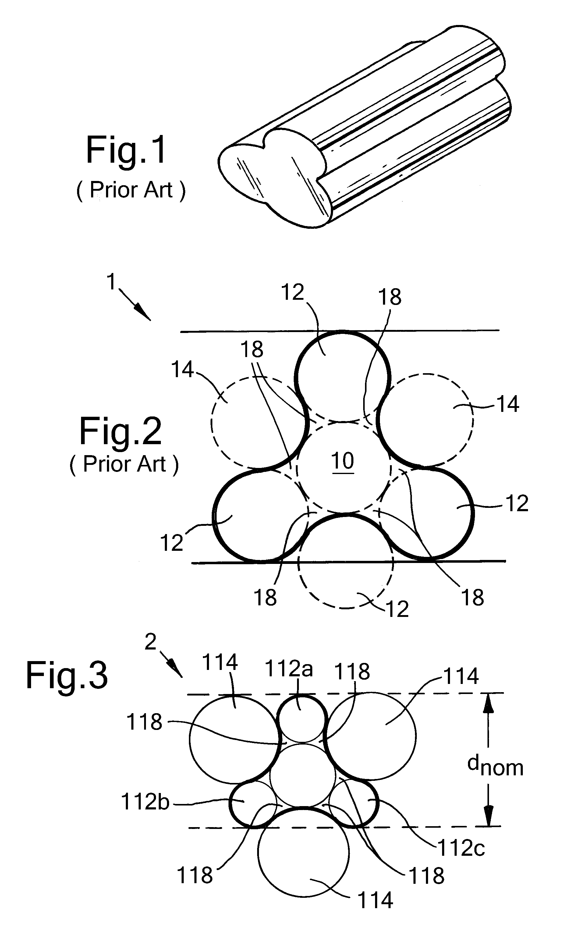
[0102]The cross-section of a preferred embodiment of a catalyst, catalyst precursor, or catalyst carrier according to the present invention is presented in FIG. 3. The shape is defined by a central circle 110 surrounded by six outer circles 112, 114. Only circles 110, 112 are occupied, not circles 114. Interstitial areas 118 are also occupied.

[0103]The central circle 110 has a diameter which is 1.5 times larger than that of the outer occupied circles 112. The unoccupied circles 114 have a diameter which is twice the diameter of the occupied outer circles 112. This shape of extrudate provides a surprising balance between sufficient strength whilst also minimizing diffusion limitation within a fixed bed multitubular reactor.

[0104]The nominal diameter ‘d nom’ is the length from the furthest point on one outer occupied circle 112a through the centre of the central circle 110 extending to a line drawn between the bottom of each of the remaining outer occupied circles 112b, 112c.

example 2

[0105]A Fischer-Tropsch catalyst according to the present invention was prepared comprising cobalt (as catalytically active metal), manganese (as promoter), and titania (as catalyst carrier). The shape of the cross-section of the Fischer-Tropsch catalyst particles was as shown in FIG. 3. The average length of the particles was 1.7 mm.

[0106]A comparative Fischer-Tropsch catalyst was prepared comprising cobalt (as catalytically active metal), manganese (as promoter), and titania (as catalyst carrier). The shape of the Fischer-Tropsch catalyst particles was like the shape shown in FIG. 1 (TL-shape). The average length of the particles was 1.7 mm.

[0107]The CO2 selectivity for these catalysts was tested. CO2 is an unwanted by-product and is preferably minimized.

[0108]At a comparable operating temperature and comparable productivity, unwanted CO2 production is 33% lower on the catalyst in accordance with the present invention as compared to the comparative TL-shaped catalyst.

[0109]Indeed ...

example 3

[0110]A Fischer-Tropsch catalyst according to the present invention was prepared comprising cobalt (as catalytically active metal), manganese (as promoter), and titania (as catalyst carrier). The shape of the cross-section of the Fischer-Tropsch catalyst particles was as shown in FIG. 3. The average length of the particles was 1.7 mm.

[0111]A comparative Fischer-Tropsch catalyst was prepared comprising cobalt (as catalytically active metal), manganese (as promoter), and titania (as catalyst carrier). The shape of the cross-section of the Fischer-Tropsch catalyst particles was as shown in FIG. 2 (Tx-shape). The average length of the particles was 1.7 mm.

[0112]Regarding strength, the attrition index of both catalysts was determined by rotating the catalyst particles within a drum with one internal baffle plate, over a standard number of drum rotations. The loss of material was then determined as the change in weight of material below 0.84 mm, judged as being “fines”.

[0113]The attrition...


PUM

PropertyMeasurementUnit
diameteraaaaaaaaaa
temperatureaaaaaaaaaa

Abstract

A catalyst, catalyst precursor, or catalyst carrier formed as an elongated shaped particle having a cross section comprising three protrusions each extending from and attached to a central position. The central position is aligned along the longitudinal axis of the particle. The cross-section of the particle occupies the space encompassed by the outer edges of six outer circles around a central circle, each of the six outer circles contacting two neighbouring outer circles, the particle occupying three alternating outer circles equidistant to the central circle and the six interstitial regions, the particle not occupying the three remaining outer circles which are between the alternating occupied outer circles. The ratio of the diameter of the central circle to the diameter of the outer occupied circle is more than 1, and the ratio of the diameter of the outer unoccupied circle to the diameter of the outer occupied circle is more than 1. The ratio of the diameter of the outer unoccupied circle to the diameter of the outer occupied circle is more than the ratio of the diameter of the central circle to the diameter of the outer occupied circle.

Description

[0001]The present application claims the benefit of European Application 07100746.2 filed Jan. 18, 2007.BACKGROUND OF THE INVENTION[0002]This invention relates to a catalyst, catalyst precursor, and catalyst carrier of a particular cross sectional shape for use in catalysing reactions, particularly mass transfer limited reactions, such as Fischer-Tropsch reactions or hydrocracking reactions.[0003]The Fischer-Tropsch process can be used for the conversion of synthesis gas (from hydrocarbonaceous feed stocks) into liquid and / or solid hydrocarbons. Generally, the feed stock (e.g. natural gas, associated gas and / or coal-bed methane, heavy and / or residual oil fractions, coal, biomass) is converted in a first step into a mixture of hydrogen and carbon monoxide (this mixture is often referred to as synthesis gas or syngas). The synthesis gas is then fed into one or more reactors where it is converted in one or more steps over a suitable catalyst at elevated temperature and pressure into ma...

Claims


Application Information

Patent Timeline
Patent Type & Authority Applications(United States)
IPC IPC(8): B32B5/16B01J32/00B01J37/00C07C1/04
CPCB01J21/06B01J21/063B01J23/40B01J23/74B01J23/745B01J23/75Y10T428/2982B01J23/8892B01J35/026B01J37/0009C10G2/332C10G47/02B01J23/8472
Inventor CALIS, HANS PETER ALEXANDERVERBIST, GUY LODE MAGDA MARIA
Owner SHELL OIL CO
Why Eureka
Try Eureka