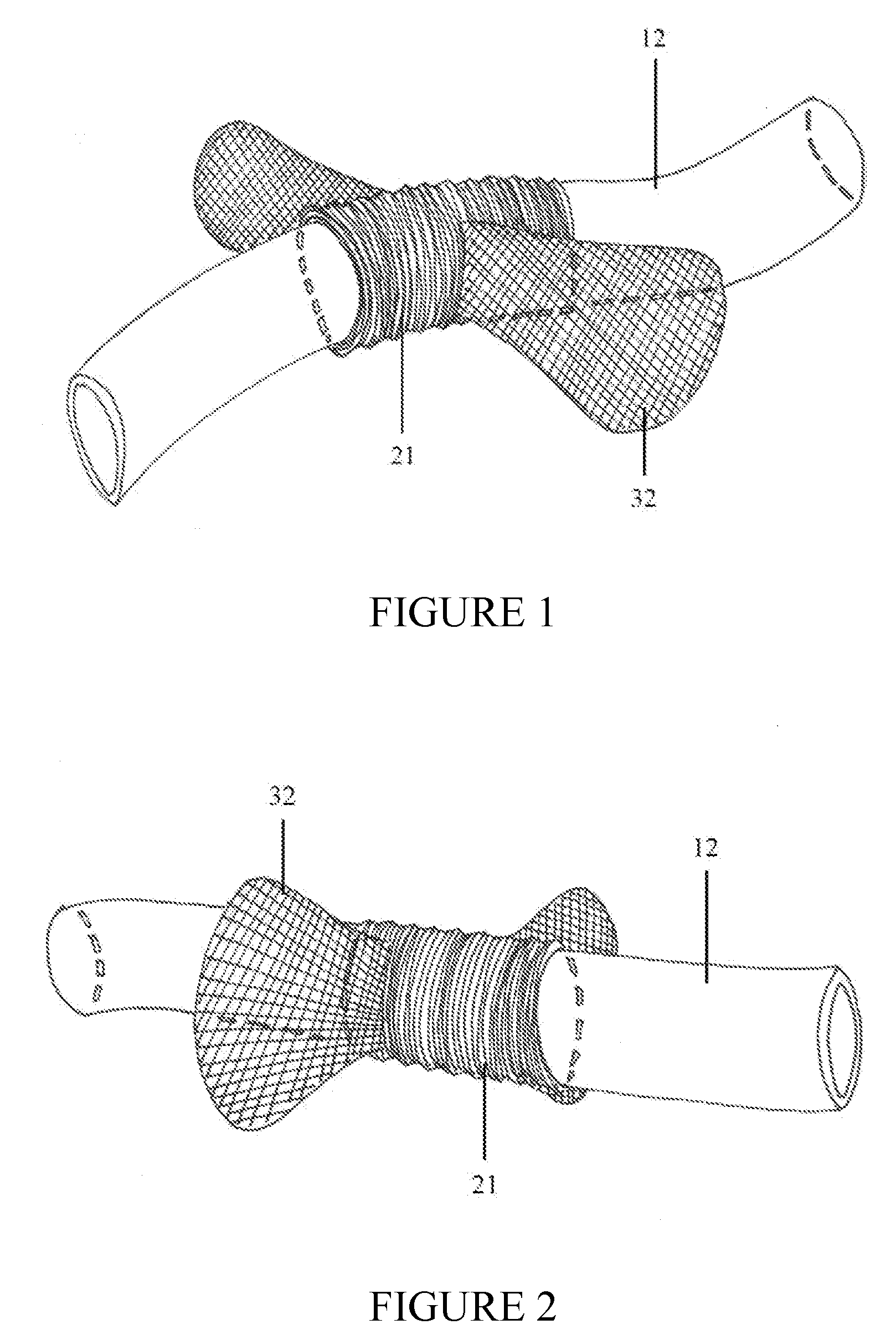
Securement device for shunt catheter and implantation method therefor

a secure device and shunt catheter technology, applied in the field of shunt catheters, can solve the problems of shunts commonly molded from silicone tubing, easy failure, and fatality, and achieve the effects of less susceptible, enhanced csf flow, and reduced incidence of shunt malfunction

Inactive Publication Date: 2008-10-23
CEREBRO DYNAMICS INC
View PDF24 Cites 31 Cited by
  • Summary
  • Abstract
  • Description
  • Claims
  • Application Information

AI Technical Summary

Benefits of technology

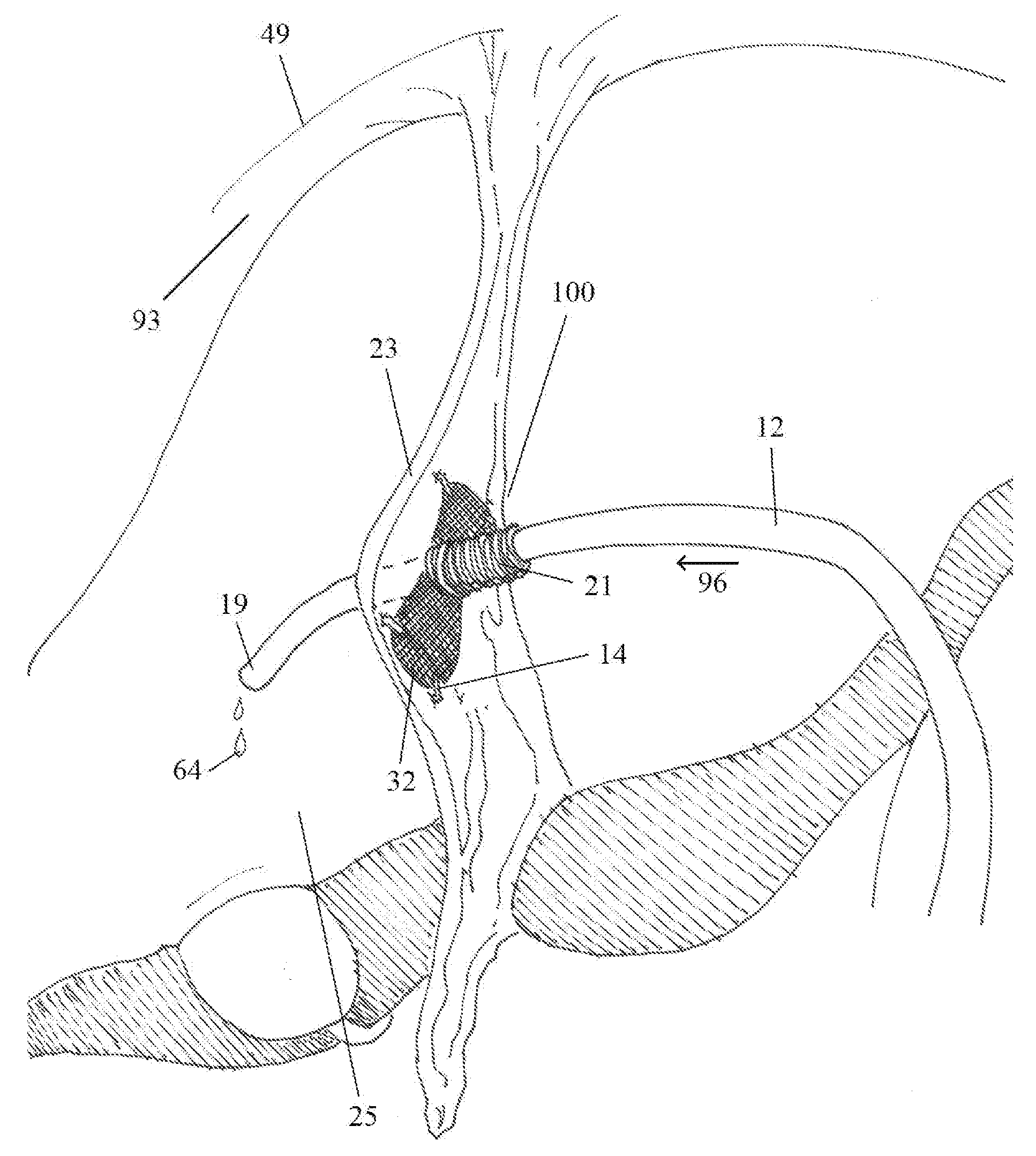
[0029]Further embodiments may be composed of a more elongated cuff with opposing paired flanges, discs or a combination of a disc and a flange. Staple or suture fixation to the target anatomic structure may or may not be used with such embodiments. For example, the flanges on the leading edge of the cuff in a dual-flanged embodiment, composed of deformable material, may be passed through the created fenestration in a falciform ligament. The flanges will serve to resist potential catheter pullout by their expansibility and large size relative to the created fenestration in the falciform ligament. Similarly, those flanges on the trailing edge of the cuff will prevent the distal shunt catheter from advancing into the right abdominal gutter. In this recess, bordered laterally by the abdominal wall and medially by the liver, obstructive debris or fluid pockets may reside and potentially obstruct the distal tip of the shunt catheter. The embodiments may have a directional bias for implantation as can be observed in the figures.
[0030]The implantable systems and devices of the invention serve to secure the distal limb of the shunt catheter to a site that is relatively free of potentially obstructive soft tissue, fat, proteinaceous debris, intra-abdominal fluid pockets and intra-abdominal adhesions. The distal catheter tip is therefore less susceptible to blockage and the incidence of shunt malfunction is transitively reduced. In a preferred embodiment of the described method, the distal shunt catheter is passed through a fenestration created in the falciform ligament. A short length of distal shunt catheter emanates through the created fenestration in the ligament and ultimately lays on the superior serosal surface of the right lobe of the liver. This is a site relatively free of potentially obstructive soft tissue, fat, proteinaceous debris, free fluid and intra-abdominal adhesions in which the catheter may lay. In addition, the distal catheter tip may be better exposed to the negative pressure of the subdiaphragmatic space, with resultant enhancement of CSF flow through the shunt system as CSF shunts are typically pressure-driven systems in which the difference between intracranial and intra-abdominal pressure drives CSF flow.

Problems solved by technology

The latter may follow a more malignant course and in fact, prove fatal.
Cerebrospinal fluid shunts, commonly molded from silicone tubing, are susceptible to failure.
Such malfunctions, while often benign, may prove dangerous or, if left untreated, fatal.
The procedure and the inpatient hospitalization have associated risks and morbidity.
The distal catheter tip, often located in the peritoneal cavity, is susceptible to blockage by omental fat or proteinaceous debris.
Any potential increase in outflow resistance may result in slowed CSF flow or florid obstruction of the shunt system.
Nevertheless, the orifice of the distal shunt catheter, most often located in the peritoneal cavity, is susceptible to blockage as previously described.
This may be due to mechanical obstruction by omental fat, proteinaceous debris, intra-abdominal fluid, or intra-abdominal adhesions.
This is manifest in the fact that there is an increased incidence of distal shunt malfunction in constipated patients.
Though elaborate in design, such a mechanism, by virtue of its intricate structure and reliance on small mobile components, may be susceptible to mechanical failure.
Bron does not address the etiology of shunt malfunction in adults, namely occlusion of the distal catheter which typically is inserted into the peritoneal cavity (abdominal cavity).
While it may be the case that said plug reduces the incidence of malfunction within those shunts incorporating slit valves, such valves in general are associated with a higher incidence of distal malfunction.
It is concluded therefore that side slits in the distal peritoneal catheters of VP shunts are associated with a greater incidence of distal shunt obstruction.
Currently, no implantable device exists to maintain CSF flow in the distal limb of a shunt catheter.
The prior art does not address the root problem of catheter migration.

Method used


Image

  • Securement device for shunt catheter and implantation method therefor
  • Securement device for shunt catheter and implantation method therefor
  • Securement device for shunt catheter and implantation method therefor

Examples


Embodiment Construction

[0082]For purposes of clarity and brevity, like elements and components bear the same designations and numbering throughout the Figures.

[0083]FIG. 1 is a side view of an implantable device with a traversing peritoneal shunt catheter. In a preferred embodiment, cuff 21 is a circumferential sleeve of pliable material such as VELCRO®, TEFLON® or nylon mesh. Alternate materials such as urethane or silicone can also be utilized. Radio-opaque materials or dyes can be incorporated into cuff 21 to allow for x-ray localization of the implantable system. Generally, cuff 21 has a circular, cross-sectional shape. Distal shunt catheter (intraperitoneal) 12 traverses circumferential cuff 21. The inner diameter of cuff 21 approximates the outer diameter of distal shunt catheter (intraperitoneal) 12 thereby assuring a tight interface between said elements. Such a snug, secure fit is necessary to prevent catheter dislodgement and resultant catheter migration. To promote this tight interface, distal ...


PUM


Abstract

The invention relates to implantable systems for securing shunt catheters. The implantable system and device functions to maintain shunt patency and thus, shunt catheter malfunction due to obstruction is prevented

Description

CROSS REFERENCE TO RELATED APPLICATIONS[0001]This application claims the benefit under 35 U.S.C.119(e) of U.S. provisional patent application Ser. No. 60 / 913,460, filed Apr. 23, 2007, and U.S. provisional patent application, Ser. No. 61 / 027,726, filed Feb. 11, 2008, the contents of which are each herein incorporated by reference.FIELD OF THE INVENTION[0002]The present invention relates generally to shunt catheters, particularly to cerebrospinal fluid (CSF) shunt catheters used in the treatment of hydrocephalus, and most particularly to the prevention of cerebrospinal fluid shunt catheter malfunction.BACKGROUND OF THE INVENTION[0003]Hydrocephalus is the pathologic accumulation of cerebrospinal fluid (CSF) in the brain. The disease entity has a variety of clinical manifestations ranging from the more benign triad of normal pressure hydrocephlalus (gait ataxia, dementia and urinary incontinence) to those secondary to elevated intracranial pressure. The latter may follow a more malignan...

Claims


Application Information

Patent Timeline
Patent Type & Authority Applications(United States)
IPC IPC(8): A61M5/00
CPCA61M25/04A61M27/006A61M2025/0233
Inventor WIENER, EDWARD LEE
Owner CEREBRO DYNAMICS INC
Why Eureka
Try Eureka