

Method For Providing a Polymeric Implant With a Crystalline Calcium Phosphate Coating
a polymer implant and calcium phosphate technology, applied in dental prosthetics, dental preparations, impression caps, etc., can solve the problems of high temperature resistance of polymers, high polymer temperature, and strong disadvantages of annealing procedures
- Summary
- Abstract
- Description
- Claims
- Application Information
AI Technical Summary
Benefits of technology
Problems solved by technology
Method used
Image

Examples
examples
Experimental Techniques
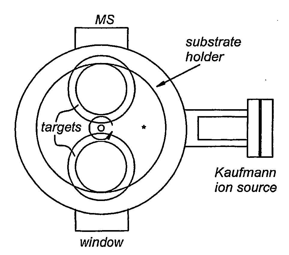
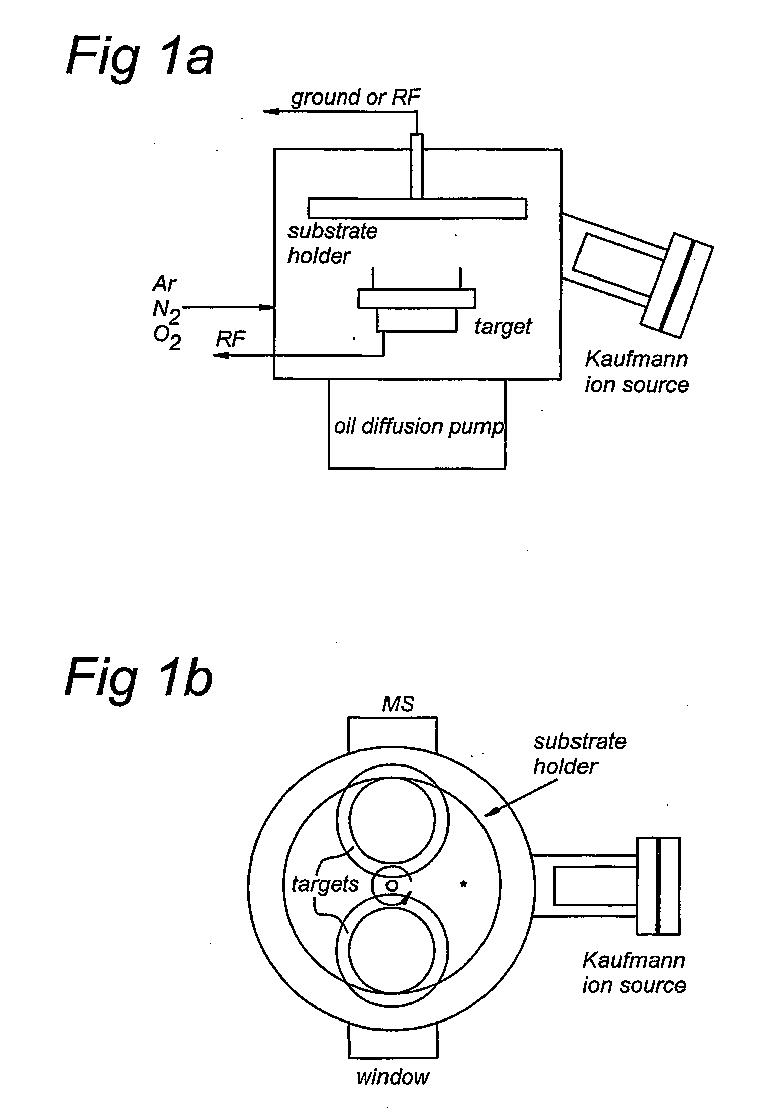
RF Magnetron Sputter Deposition
[0043]Sputter deposition is based on the ejection of species from a target by highly energetic particles. The energetic projectiles can be generated using an ion gun or plasma. The ejected species end up on the substrates to form a coating.
[0044]In RF sputter deposition, the projectiles are generated by an RF plasma. An RF instead of a DC field is often used in case of an insulating target, to avoid charging and arcing. Electrons that follow the alternating RF field cause ionizations of the gas in the vacuum chamber. Positive ions that form in the plasma (often argon ions) are accelerated when they cross the so-called plasma sheaths, which is a sudden drop in potential at the edges of the plasma. The accelerated ions cause the ejection of species from the sputter target and they also initiate the ejection of secondary electrons, which are responsible for additional ionizations in order to maintain the plasma.
[0045]The sputtering ...
PUM
| Property | Measurement | Unit |
|---|---|---|
| Thickness | aaaaa | aaaaa |
| Thickness | aaaaa | aaaaa |
| Nanoscale particle size | aaaaa | aaaaa |
Abstract
Description
Claims
Application Information