
Oli composition for cutting and grinding by minimal quantity lubrication system

a lubrication system and composition technology, applied in the direction of mechanical equipment, group 3/13 element organic compounds, manufacturing tools, etc., can solve the problems of reducing working efficiency, sticking, handling troubles, etc., and achieve the effect of reducing the wear of tools, improving cutting and grinding efficiency, and improving the finished surface of workpieces

Inactive Publication Date: 2008-10-30
NIPPON OIL CORP
View PDF3 Cites 0 Cited by
  • Summary
  • Abstract
  • Description
  • Claims
  • Application Information

AI Technical Summary

Benefits of technology

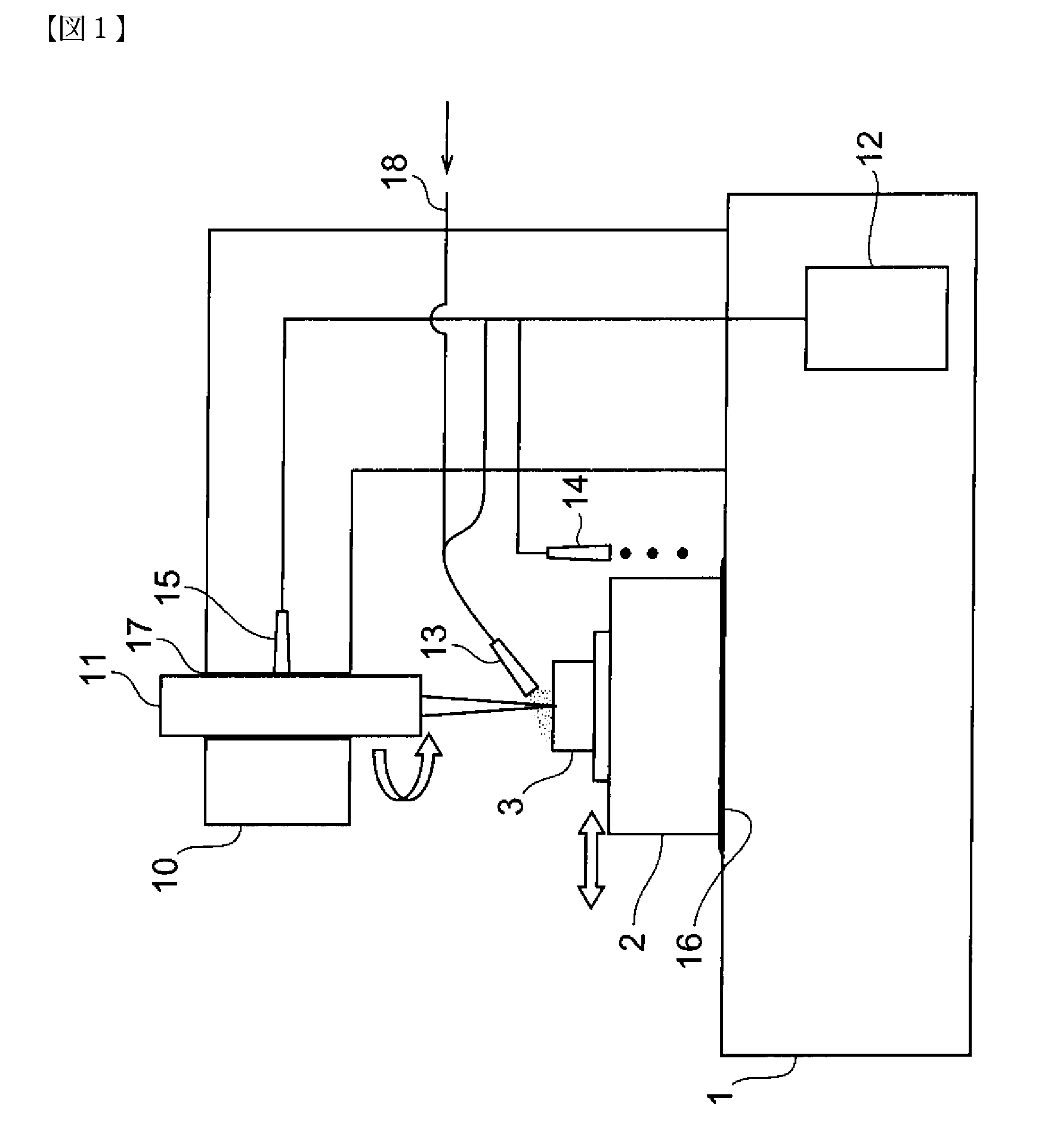
[0010]A method for cutting and grinding by minimal quantity lubrication system is preferably expected to provide a better finished surface of workpieces, reduction of the wear of tools, and high efficiency of cutting and grinding even though the volume of the oil feed is extremely low. Therefore, this method requires the higher performance of the oil for cutting and grinding. In addition, it is preferable that the oil should be biodegradable from the viewpoint of waste disposal and working environment.
[0011]Further, in the minimal quantity lubrication system, oil is supplied in the form of mist. If the oil is unstable, it deposits on the surface of the inside of machine tools, workpieces, tools and mist collectors, which causes stickiness phenomenon. This leads to the handling troubles and reduces working efficiency. Therefore, the low level of stickiness is a desirable property of the oil used for the minimal quantity lubrication system.
[0013]The present invention was executed in such circumstances and the object of the present invention is to provide a lubricating oil which can improve working efficiency, tool life and handling in the method of cutting and grinding by minimal quantity lubrication system.

Problems solved by technology

If the oil is unstable, it deposits on the surface of the inside of machine tools, workpieces, tools and mist collectors, which causes stickiness phenomenon.
This leads to the handling troubles and reduces working efficiency.
However, it is quite difficult to satisfy all of the aforementioned requirements with good balance even though the conventional oils are used as they are for the minimal quantity lubrication system.

Method used


Image

  • Oli composition for cutting and grinding by minimal quantity lubrication system
  • Oli composition for cutting and grinding by minimal quantity lubrication system
  • Oli composition for cutting and grinding by minimal quantity lubrication system

Examples


examples

[0116]The following examples and comparative example further illustrate the detail of the present invention, but do not serve to limit the scope of the invention in any way.

examples 1 to 19

, Comparative Examples 1 to 3

[0117]Oils of Examples 1 to 19 and Comparative Examples 1 to 2 shown in Tables 1 and 2 were prepared by using the following substances; base oil, phosphorus compounds, sulfur compounds and antioxidant.

[0118](Base Oil)

a: Triester of neopentylglycol and oleic acid

b: Triester of trimethylolpropane and oleic acid

c: Tetraester of trimethylolpropane and acid mixture of n-hexanic acid / n-octanic acid / n-decanic acid (mixing mole ratio=7:59:34)

d: Tetraester of pentaerythritol and n-octanic acid

e: Commercially available rapeseed oil

f: Monoester of glycerol and oleic acid

[0119](Sulfur Compounds)

g: Sulfide ester (Sulfur content: 9.9% by mass, inactive)

h: Polysulfide (Sulfur content: 36% by mass, active)

[0120](Phosphorus Compounds)

i: Tricresylphosphate

[0121]j: Di-2-ethylhexylphosphate

[0122](Anti-Oxidant)

k: 2,6-di-tert-butyl-p-cresol

[0123]Next, the following evaluation tests were carried out using the prepared oils. Note that the Comparative Example 3 was evaluated in ...


PUM

PropertyMeasurementUnit
temperatureaaaaaaaaaa
kinematic viscosityaaaaaaaaaa

Abstract

An oil composition for cutting and grinding by minimal quantity lubrication system and for sliding surface according to the present invention comprises an ester and a sulfur compound and / or a phosphorus compound.

Description

TECHNICAL FIELD[0001]The present invention relates to an oil composition for cutting and grinding by minimal quantity lubrication system, and more particularly, relates to a oil composition to be used for a cutting and grinding method of workpiece to be machined while supplying minimal quantity oil together with a compressed fluid to a spot of machining.BACKGROUND ART[0002]Various cutting or grinding oils are generally used to improve the productivity of machining which extends the life of tools for machining such as drills, endmills, turning tools and grinding wheels, and improves the roughness of machined surface and the machining efficiency thereby.[0003]Oils for cutting and grinding are roughly classified into two types; water-soluble ones which are used after diluting the surface-active agent and lubricant component contained therein with water, and water-insoluble ones which contain a mineral oil as a main component and are used as it is. In conventional cutting and grinding o...

Claims


Application Information

Patent Timeline
Patent Type & Authority Applications(United States)
IPC IPC(8): C10M141/10C10M105/38B23Q11/10C10M169/04
CPCB23Q11/10C10M169/04C10M2207/2805C10M2207/281C10M2207/2815C10M2207/282C10M2207/2825C10M2207/283C10M2207/2835C10M2207/286C10M2207/301C10M2207/34C10M2207/345C10M2207/40C10M2207/401C10M2207/404C10M2207/4045C10M2219/064C10M2219/068C10M2219/08C10M2223/04C10M2223/041C10M2223/043C10M2223/045C10M2223/047C10M2223/049C10N2210/02C10N2210/06C10N2230/06C10N2230/10C10N2240/02C10N2240/04C10N2240/401C10N2260/10C10M101/04C10M105/32C10M135/16C10M137/10F16C2240/02B23Q11/1061C10N2010/04C10N2010/12C10N2030/06C10N2030/10C10N2040/02C10N2040/04C10N2040/22C10N2060/10
Inventor YOKOTA, HIDEOIBI, MASANORISUDA, SATOSHI
Owner NIPPON OIL CORP
Learn More