Proton beam therapy control system

a control system and proton beam technology, applied in the field of distributed control systems, can solve the problems of localized cell damage, damage to other healthy cells within the patient's body, and disrupt the growth and progression of tumors, so as to reduce channel or socket utilization, reduce communication coordination and management complexity, and increase connection security

Inactive Publication Date: 2008-10-30
LOMA LINDA UNIV MEDICAL CENT
View PDF2 Cites 24 Cited by
  • Summary
  • Abstract
  • Description
  • Claims
  • Application Information

AI Technical Summary

Benefits of technology

[0019]Communications coordination and management complexity is significantly reduced using the tiered communications system. In one aspect, the communications system architecture reduces channel or socket utilization by multiple processes using a routing / multiplexing functionality of the agent to resolve potential bottlenecks encountered coordinating data exchange between the hardware devices. The communications system further provides a constant monitoring capability for embedded systems using a proctor module.
[0020]A centralized connection architecture provides a further benefit of increased connection security which is important in maintaining the safety of patients treated using the proton beam therapy system. The communications system architecture additionally simplifies user interfacing and reduces the complexity of application development and deployment. For example, host applications can be configured to manage, monitor, and control embedded hardware devices without specific knowledge of the functional implementation or definitions required to communicate with each device. Additionally, the host applications can be configured to communicate with the embedded hardware devices without knowing the physical location of the device or its controlling system. In one aspect, logical mapping of this nature permits the flexible placement of devices within the system without substantial modification to the system configuration.

Problems solved by technology

The energy from the stream results in localized cell damage and effectively disrupts the growth and progression of the tumor.
Otherwise, the stream could damage other healthy cells within the patient's body.
Together these systems form a complex and distributed collection of hardware and software components.
Additionally, in a proton treatment facility with more than one treatment apparatus, the complexity of the system is further increased by the additional requirements for system redundancy and selective control of each treatment apparatus.
The complex architecture of distributed systems such as radiation therapy devices present numerous obstacles in allowing for coordinated control by a single application and further create networking difficulties between the components of the system.
One particular limitation of conventional distributed systems relates to the management of data communications between the various components of the distributed system which becomes more difficult as the size of the distributed system increases.
This problem is particularly apparent when a radiation therapy device is designed to contain more than one treatment apparatus.
As a result, providing a centralized control and monitoring solution becomes a cumbersome task due in part to the number of communications channels which must be maintained.
Additionally, the complex communications mapping schema presents difficulties in insuring that all devices can communicate with one another.
Oftentimes, modifying or upgrading a single component of the distributed system necessarily results in the need to modify the configuration for a large number of other components to which the modified component was connected.
Improper modification of the configuration for these components can result in numerous problems including loss of system control, inaccurate system monitoring, and device failure.
In a radiation therapy device, significant reconfiguration of the existing mapping schema in the aforementioned manner is undesirable as it introduces potential control issues which must be resolved in order to insure patient safety.
If these issues are not properly resolved or if there is unexpected loss of control of one of more of the components during operation of the radiation therapy device, patient injury may occur.
A number of difficulties arise when using this approach which limit the coordination and management capabilities of complex distributed systems such as radiation therapy devices.
In many instances this results in increased system overhead necessary to manage the communication channels 70 which may grow to a point where the maximum number of communication channels 70 supported by the operating system or hardware components is exceeded.
Thus, conventional distributed systems 40 provide limited scalability due to restrictions in the number of communications channels 70 which can be accommodated.
Additionally, as the complexity of the distributed system 40 increases it becomes more difficult to perform effective network monitoring and authentication as well as maintain secure firewall policies to insure adequate system security.
Conventional approaches insufficiently address this problem and rely on esoteric mapping schemes which may be difficult to understand and develop around.
This method of information distribution and coordination is undesirable for a number of reasons, including the above-described maintenance difficulties, lack of scalability, and increased complexity in data verification and validation.
One potential drawback using this approach is that a failure of the host application or the controlling program may result in a potentially unsafe or hardware-damaging condition.
In some instances a “watchdog” program is employed to detect lapses in communication between the host application and the monitored hardware however the use of a watchdog program may have undesirable effects on the system.
This may result in the cooling of the power supply and subsequently result in a lengthy warm up period before patient treatment can resume.
Furthermore, a failure in the proton beam therapy system may be masked until just prior to treatment, possibly delaying the treatment and adding to the discomfort of the patient.

Method used


Image

  • Proton beam therapy control system
  • Proton beam therapy control system
  • Proton beam therapy control system

Examples


Embodiment Construction

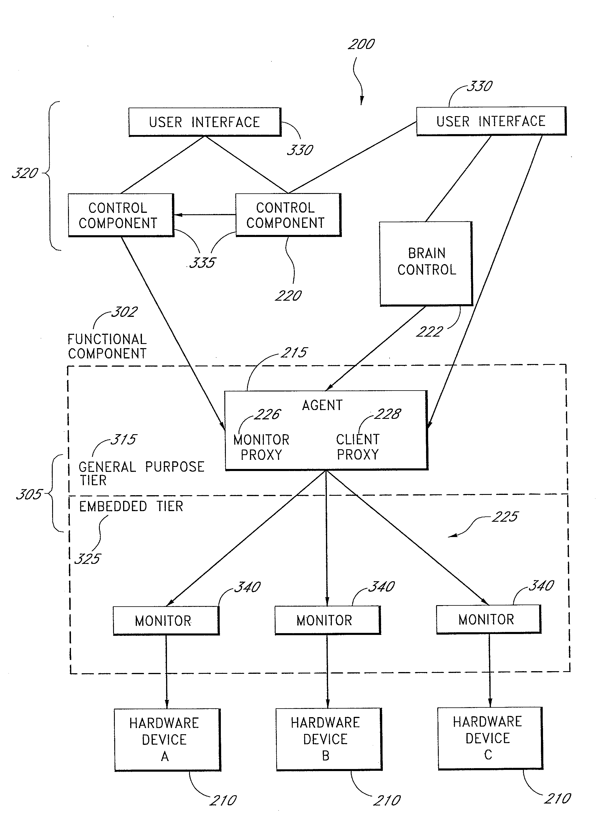
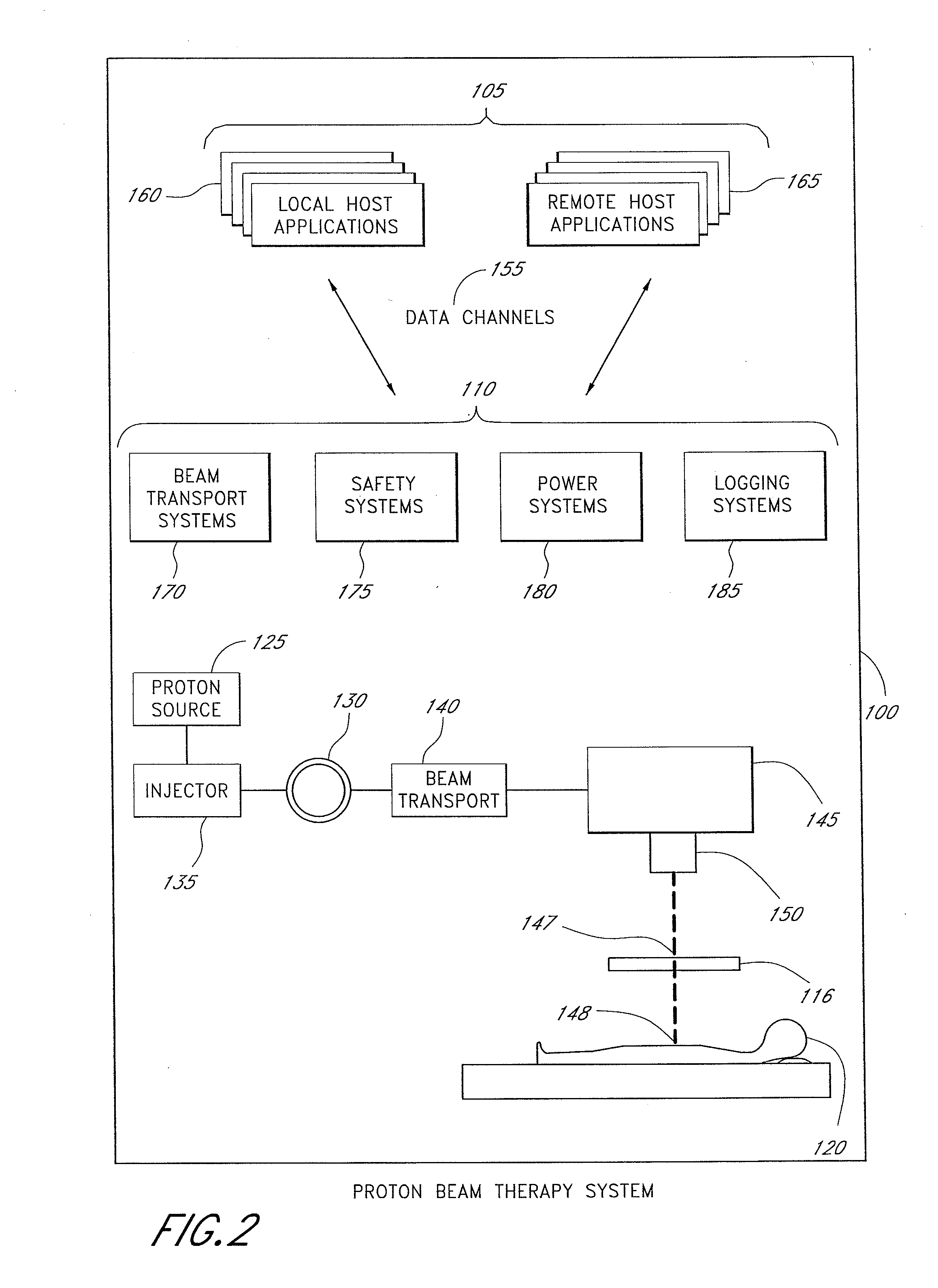
[0036]FIG. 2 illustrates one embodiment of a proton beam therapy system (PBTS) 100 for patient treatment that is coupled to one or more host applications 105. In one aspect, the host applications 105 communicate with a plurality of functional components 110 used in conjunction with a treatment station 115. The functional components 110 comprise monitoring and management components that direct the activities of the treatment station 115. Each functional component 110 further comprises one or more hardware devices present in the treatment station 115 which are desirably associated and collectively managed within the particle beam therapy system 100.

[0037]During the treatment process, the operation of these hardware devices are desirably coordinated to direct a precisely calibrated and aligned proton beam 147 towards a specific target region or isocenter 148 of the patient 120. In one embodiment, the treatment station 115 comprises a proton source 125 connected to an accelerator 130 by...


PUM


Abstract

A tiered communications architecture for managing network traffic in a distributed system. Communication between client or control computers and a plurality of hardware devices is administered by agent and monitor devices whose activities are coordinated to reduce the number of open channels or sockets. The communications architecture also improves the transparency and scalability of the distributed system by reducing network mapping dependence. The architecture is desirably implemented in a proton beam therapy system to provide flexible security policies which improve patent safety and facilitate system maintenance and development.

Description

CLAIM OF PRIORITY[0001]This U.S. patent application is a continuation of U.S. patent application Ser. No. 10 / 433,817 filed Nov. 28, 2003 which was the U.S. National Phase application of PCT / US01 / 47634 filed Dec. 10, 2001 which claims priority to U.S. Provisional Patent Application No. 60 / 254,467, entitled “Proton beam therapy system control system client / agent / monitor architecture” filed Dec. 8, 2000 which is hereby incorporated by reference.[0002]This invention was made with Government support under grant DE-FG03-98ER62632 awarded by the Department of Energy. The Government has certain rights to this invention.BACKGROUND OF THE INVENTION[0003]1. Field of the Invention[0004]The present invention relates to distributed control systems and, in particular, concerns a control system for managing data communications in a distributed environment for a proton beam therapy device.[0005]2. Description of the Related Art[0006]Radiation particle therapy devices are commonly used to treat local...

Claims


Application Information

Patent Timeline
Patent Type & Authority Applications(United States)
IPC IPC(8): G06F15/16A61N5/10G06F9/46G06F15/00G16Z99/00H04L29/08
CPCA61N5/10A61N5/1079A61N2005/1074A61N2005/1087G06F19/3406H04L67/12H04L67/32H04L69/329G16H40/63G16Z99/00H04L67/60
Inventor BAUMANN, MICHAEL A.BELOUSSOV, ALEXANDRE V.BAKIR, JULIDEARMON, DEGANITOLSEN, HOWARD B.SALEM, DANA
Owner LOMA LINDA UNIV MEDICAL CENT
Why Eureka
Try Eureka