High rate electrochemical devices

Inactive Publication Date: 2008-11-13
BRICOLEUR PARTNERS LP
View PDF3 Cites 16 Cited by
  • Summary
  • Abstract
  • Description
  • Claims
  • Application Information

AI Technical Summary

Benefits of technology

[0011]When immersed within an electrolyte, the metal particles can float freely and can substantially infuse into the porous/reticulate metal plate to create an electrode with extremely high surface area.
[0012]The electrodes in this invention can be applied to a variety of devices, including a hydrogen generation electrode in a water electrolyzer system. In such an embodiment, the electrode can function as a fluidized bed. At least one advantage is that the electrode can be operated at currents (rates) exceeding 1 A/cm2 and efficiencies in excess of 65% (measured by voltammetric or galvanometric electrochemical testing.), which in turn means that large amou

Problems solved by technology

Typical electrodes have a far lower surface area and thus cannot opera

Method used


Image

  • High rate electrochemical devices
  • High rate electrochemical devices
  • High rate electrochemical devices

Examples


example 1

Effect of Nanoparticle Addition to Upper (Cathode) Chamber

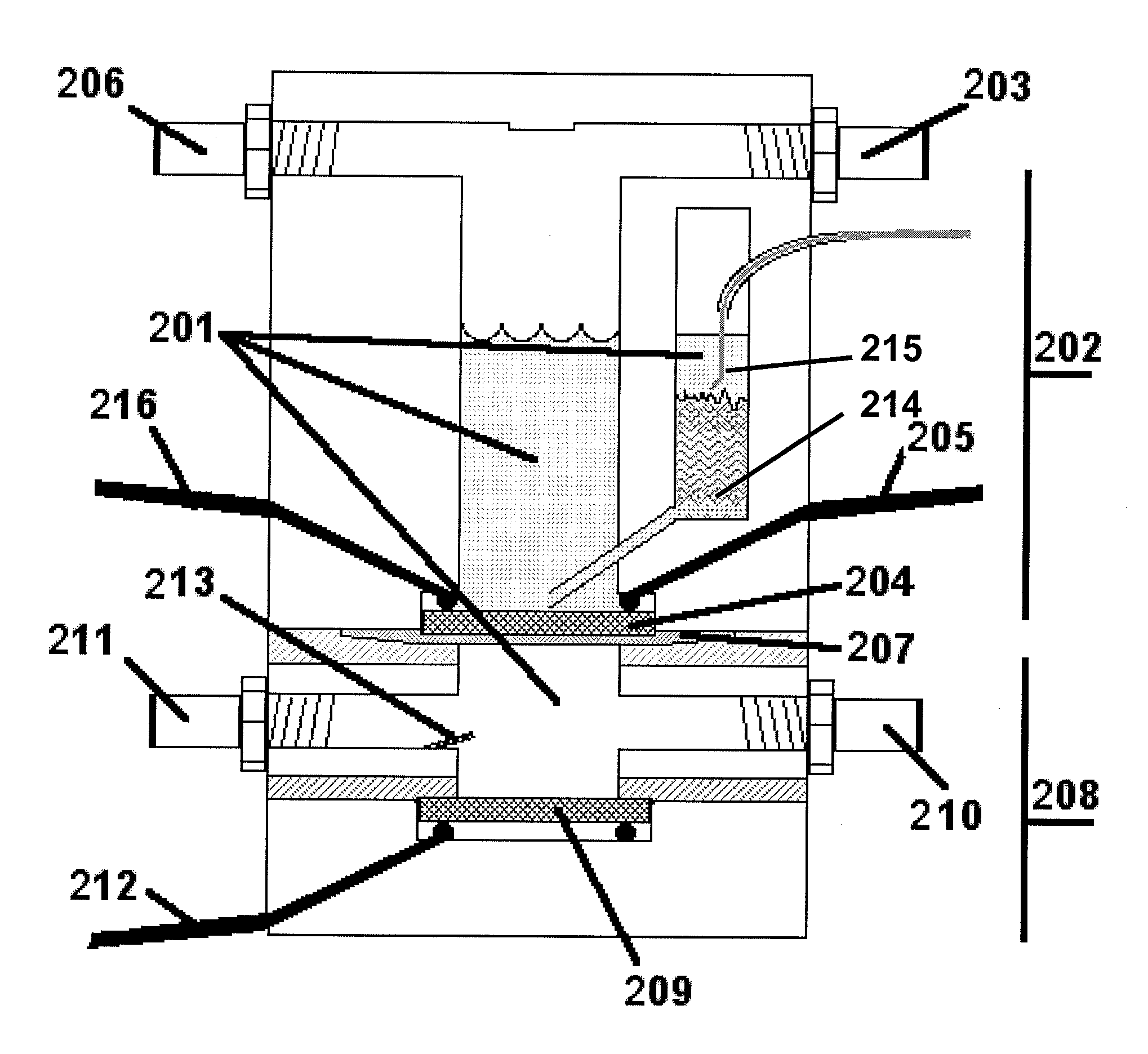
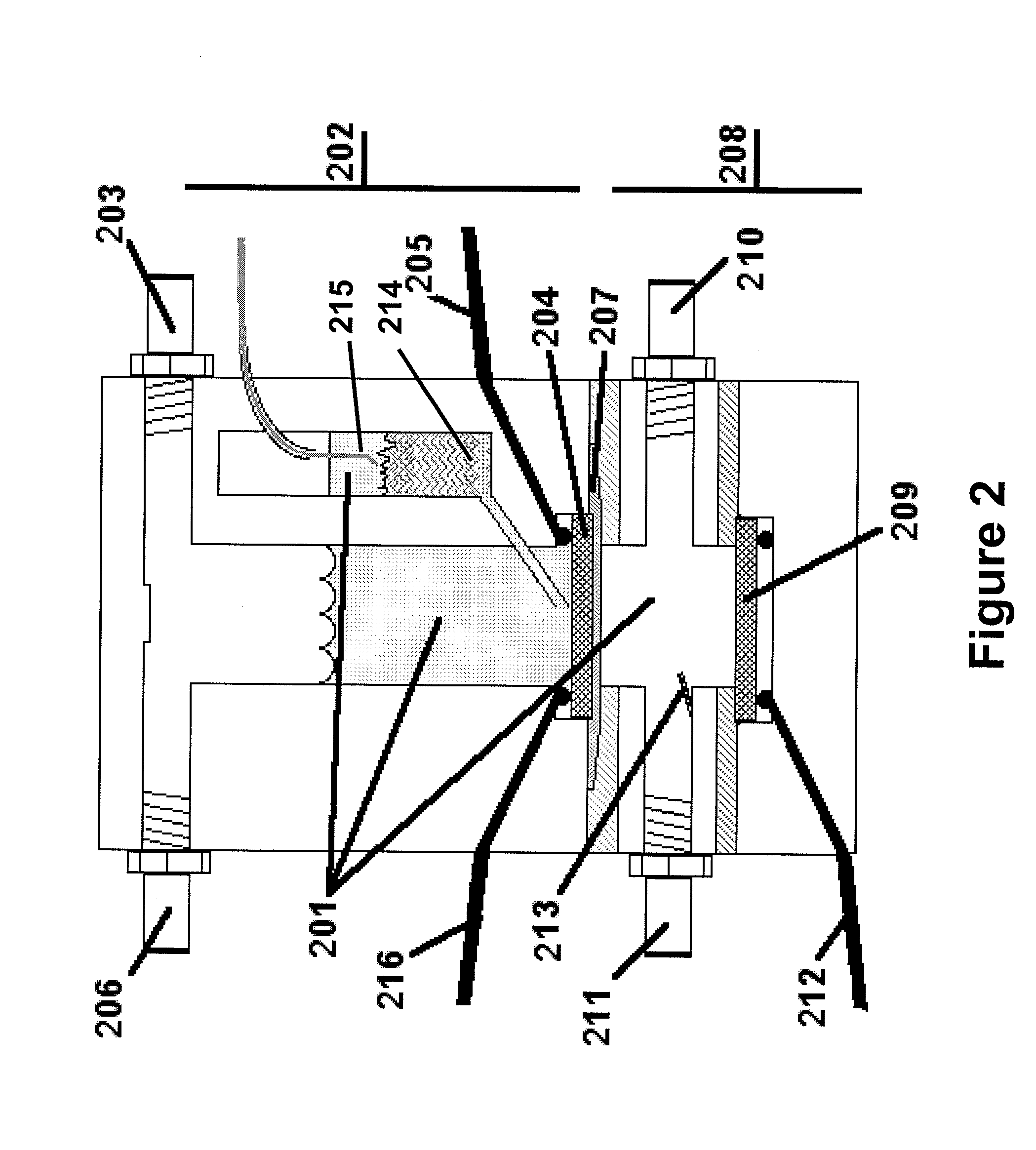
[0066]The water electrolysis device shown in FIG. 2 was used to perform the experiment. FIG. 7 illustrates the effect of injecting nano-catalyst into the upper chamber of the water electrolysis device. The electrolyzer is allowed to reach a steady-state voltage under 1 A / cm2, which is evident after about 60 seconds. At time 701, nickel nanoparticles (QSI-Nano® Nickel, 5-30 nm, from QuantumSphere Inc.) were added to the upper chamber of the electrolyzer. An efficiency increase of 10% was observed after addition of nickel nanoparticles 502. After about 15 minutes, steady state efficiency improvement was about 20%.

example 2

Comparison of Five Different Cathode Electrodes

[0067]FIG. 8 compares the performance of several different cathode electrodes for a water electrolysis device. Electrodes compared are Incofoam nickel metal foam (purchased from Inco), a sintered micron nickel plate (a sintered, compressed electrode of 1-5 micron Ni particles, purchased from Alfa Aesar), a sintered nickel plate of nickel particles (Inco 123, purchased from Inco), a sintered electrode of 5-30 nm nano-nickel from QuantumSphere Inc, and a sintered plate prepared from 1-5 micron nickel particles, as above, with 10 wt % 5-30 nm nickel from QuantumSphere Inc. injected into the electrolyte. An improvement over the base electrode 801 with no catalytic powders added was observed when micron particles were added 802 on a 1 Amp / cm2 load. This combination, however, agglomerated after less than an hour of running with significant degradation. The addition of nano-catalyst 803 increased the performance by nearly 4 times compared to t...

example 3

High Rate Capability of Electrolysis Device

[0068]FIG. 9 illustrates the improved rate capability of the electrolysis device described in the preferred embodiments relative to a more traditional system. This figure shows the voltage and current relationship of several electrode designs. Sets 901-904 are of a design compressed powders, as shown in Example 2. Sets 905-906 show the preferred embodiment. Specifically, data sets 901 / 901′ show a carbon electrode, 902 / 902′ show a smooth nickel electrode, 903 / 903′ show a compressed micron sized nickel electrode, 904 / 904′ show a micron nickel with nano sized powders added then compressed, 905 / 905′ show the preferred embodiment with no added catalyst, and 906 / 906′ show the most preferred embodiment (a foam nickel electrode with nano-nickel particles injected.) with nano-catalyst added. A voltage difference of 2 volts is about 75% efficiency. The last set of dots, 907, is a cell potential of 1,584 volts and represents over 90% efficiency when c...


PUM

PropertyMeasurementUnit
Diameteraaaaaaaaaa
Diameteraaaaaaaaaa
Diameteraaaaaaaaaa

Abstract

A device and system useful for highly efficient chemical and electrochemical reactions is described. The device comprises a preferably porous electrode and a plurality of suspended nanoparticles diffused within the void volume of the electrode when used within an electrolyte. The device is suitable within a system having a first and second chamber preferably positioned vertically or in other special arrangements with respect to each other, and each chamber containing an electrode and electrolyte with suspended nanoparticles therein. When reactive metal particles are diffused into the electrode structure and suspended in electrolyte by gasses, a fluidized bed is established. The reaction efficiency is increased and products can be produced at a higher rate. When an electrolysis device can be operated such that incoming reactants and outgoing products enter and exit from opposite faces of an electrode, reaction rate and efficiency are improved. Ideally, this device and system can be used to rapidly produce significant quantities of high purity hydrogen gas with minimal electricity cost.

Description

CROSS-REFERENCE TO RELATED APPLICATIONS[0001]This application is a continuation-in-part of application Ser. No. 11 / 716,375, filed on Mar. 9, 2007.BACKGROUND OF THE INVENTION[0002]1. Technical Field[0003]The inventions disclosed herein generally relate to improved electrochemical systems and their use and, in particular, to water electrolysis devices for the production of high purity hydrogen and oxygen, and catalysts for these devices which promote increased electrical and cost efficiency, and methods of using such devices and for the production of hydrogen and oxygen.[0004]2. Related Art[0005]Hydrogen is a renewable fuel that produces zero emissions when used in a fuel cell. In 2005, the Department of Energy (DoE) developed a new hydrogen cost goal and methodology, namely to achieve $2.00-3.00 / gasoline U.S. gallon equivalent (gge, delivered, untaxed, by 2015), independent of the pathway used to produce and deliver hydrogen. The principal method to produce hydrogen is by stream refo...

Claims


Application Information

Patent Timeline
IPC IPC(8): C25B1/02C25B9/00C25B9/18
CPCC25B1/04C25B9/162C25B11/035Y02E60/366C25B9/40C25B11/031Y02E60/36
Inventor DOPP, ROBERT BRIAN
Owner BRICOLEUR PARTNERS LP
Why Eureka
Try Eureka