Rf Power Amplifiers

a power amplifier and transistor technology, applied in the direction of amplifier modification to reduce non-linear distortion, baseband system details, gain control, etc., can solve the problems of reducing efficiency, all the amplifiers running at less than optimum efficiency, and the technique cannot be made to work with the amplifier employing field effect transistors (fets), so as to improve the characteristics of the amplifier

Active Publication Date: 2008-11-13
ASTRIUM GMBH
View PDF15 Cites 68 Cited by
  • Summary
  • Abstract
  • Description
  • Claims
  • Application Information

AI Technical Summary

Benefits of technology

[0013]An object of the present invention is to provide an amplifier system that may considerably improve characteristics of an amplifier across a wide dynamic range.

Problems solved by technology

As the amplifier drive is reduced however, the amplifier backs off and the gain becomes less compressed resulting in degraded efficiency.
When operating in active antenna arrays this results in some or all of the amplifiers running at less than optimum efficiency depending on traffic loading and beam pointing conditions (which may impose an amplitude ‘taper’ across the array, where amplifiers have a gradually reducing output amplitude across the array).
Such technique could not be made to work with amplifiers employing Field Effect Transistors (FETs) and is therefore severely limited for amplifiers in current use.
Such techniques are complicated to set up and are primarily intended to maximise the efficiency at a given back off where the amplifier has to demonstrate very high linearity.
None of the above techniques addresses the requirements of amplifiers operating in modern active array antennas.

Method used


Image

  • Rf Power Amplifiers
  • Rf Power Amplifiers
  • Rf Power Amplifiers

Examples


first embodiment

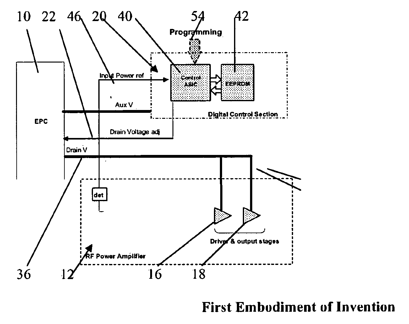
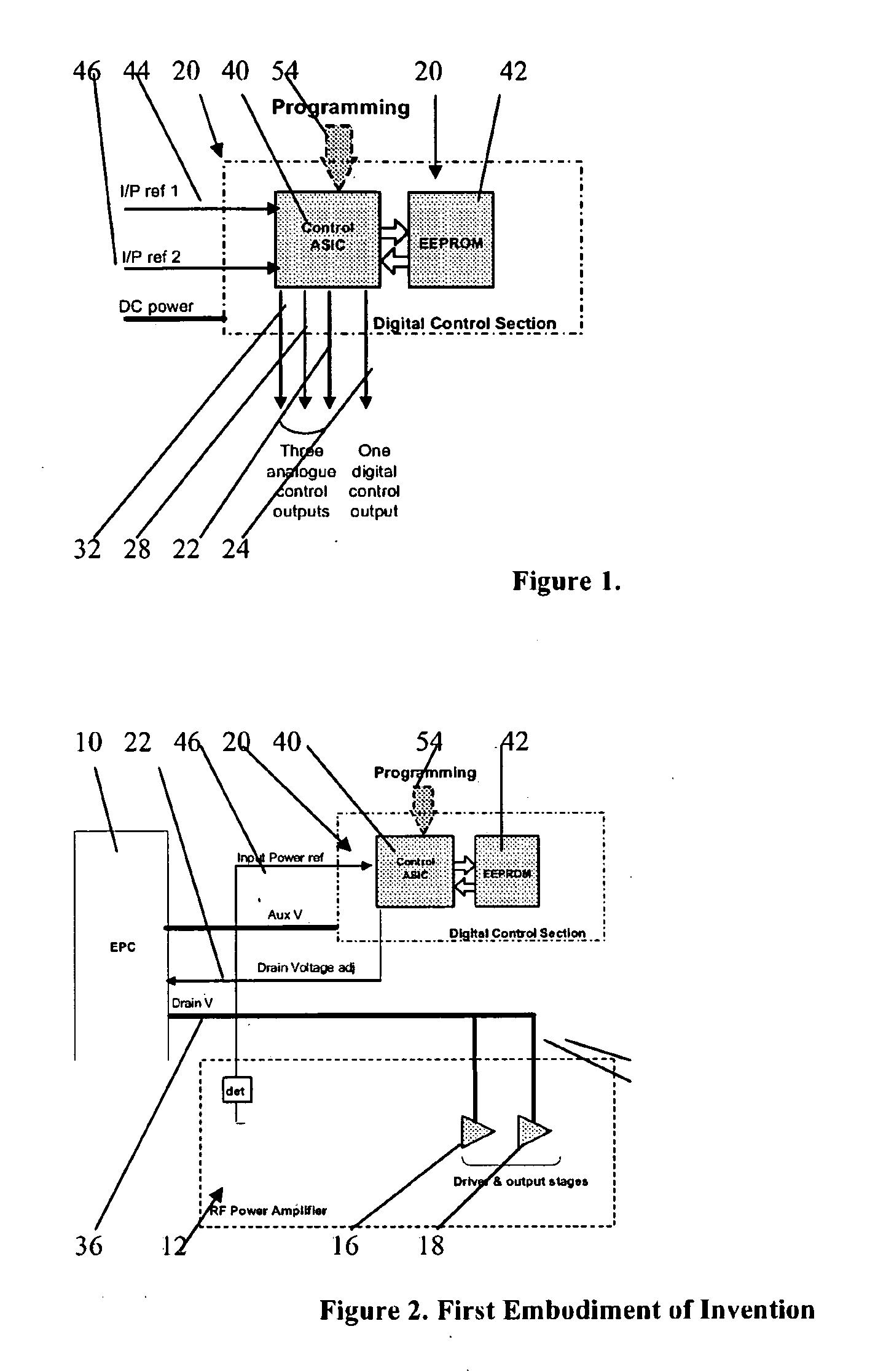
[0054]FIG. 2 illustrates the invention, similar parts to those of FIGS. 1, 9 and 10 being denoted by the same reference numeral (and for all subsequent figures). In this case the DCS 20 is supplied with a single input reference 46 from the RF amplifier 12, that being a voltage related to its input power. Only one of the DCS analogue outputs, 22, is used and this interfaces with the EPC 10 to control the main voltage supply 36 to the driver and output FET drains 16, 18. During the characterisation process the amplifier is exercised over its full input power dynamic range, and through the aforementioned software and test equipment, the EPC main output voltage 36 is digitally steered to maintain the RF amplifier driver and output stages 16, 18 at the required gain compression, in order to maintain a constant C / I ratio.

second embodiment

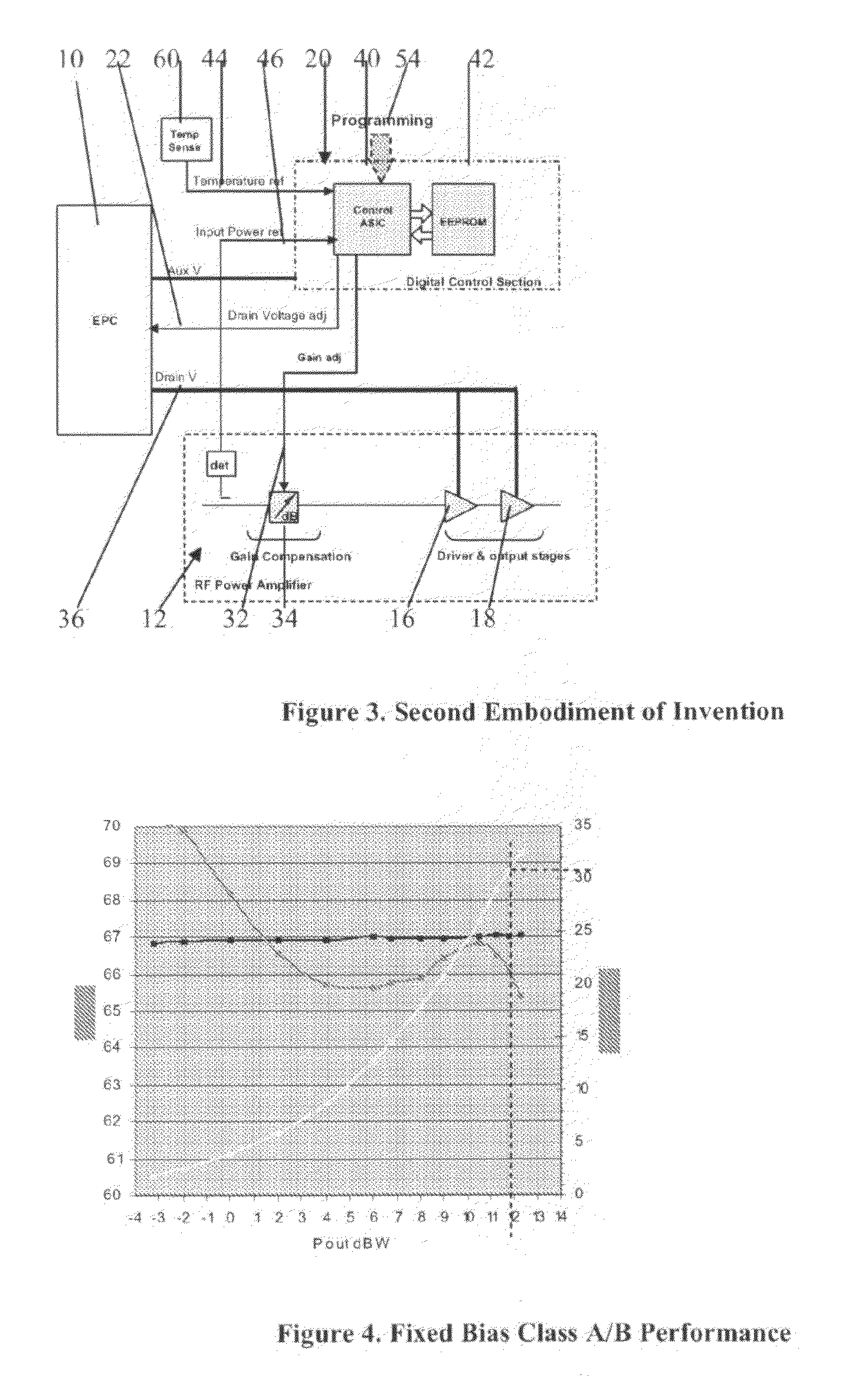
[0055]The embodiment of FIG. 2 is a minimal configuration. In practice, the amplifier gain may change as the drain supply to the driver and output FETs is adjusted and there will be temperature effects that may have to be dealt with. A second embodiment shown in FIG. 3 therefore illustrates a configuration of the invention, of more practical use, where the DCS 20 is also used to maintain the overall gain of the amplifier at a constant level over the operating dynamic range and temperature. A second reference input 44 is now supplied to the DCS 22 from a temperature sensor 60 mounted on the amplifier board, and a second analogue output 32 is used to drive a variable attenuator 34 (or other digital or analogue variable gain / loss device) in the RF chain. The characterisation process now exercises the amplifier over its full input power dynamic range and over the operating temperature range. In this way data is collected to not only adjust the gain compression with input drive, but also...


PUM


Abstract

A Solid State Power Amplifier (SSPA) for powering a single element of a multi-element antenna, the SSPA comprising:
an RF amplifier, having a signal amplifying path that includes preamplifier, driver amplifier and a power output stage;
an Electronic Power Conditioner (EPC) for providing a variable value of DC voltage for powering the power output stage of the RF amplifier;
a control ASIC for receiving an input power signal of the RF amplifier for providing a voltage control signal to the EPC to determine the value of the DC voltage, the control ASIC addressing an EEPROM holding a collection of control words that define output values of a control output signal for varying values of said input power, such that the value of the DC voltage to the power output stage is varied so as to control the gain compression of the RF amplifier for varying values of input power in order to maintain constant amplifier linearity.

Description

[0001]The present Invention relates to RF Power Amplifiers.BACKGROUND ART[0002]It is a common requirement, particularly for space satellite applications of communications, that each element of a multi-element antenna array, e.g. phased arrays, should be driven by a respective power unit, a single power amplifier. The amplified power signal for each antenna should be accurately controlled in amplitude and phase relative to the other antenna elements. It is common to employ solid state power amplifiers (SSPAs) for this purpose, but the amplifiers must meet stringent linearity, efficiency and gain / phase tracking performances required for operation in active antenna arrays.[0003]The degree of gain compression, efficiency, and linearity of an amplifier can be optimised at a given RF output power by careful selection of the bias conditions. As the amplifier drive is reduced however, the amplifier backs off and the gain becomes less compressed resulting in degraded efficiency. The linearit...

Claims


Application Information

Patent Timeline
Patent Type & Authority Applications(United States)
IPC IPC(8): H03G3/10
CPCH03F1/0211H03F1/0222H03F1/0244H03F1/0266H03F1/32H03F3/24H03F2200/105H03F2200/468H03F2201/3203
Inventor SEYMOUR, CHRISTOPHER DAVID
Owner ASTRIUM GMBH
Why Eureka
Try Eureka