Method and apparatus for cartesian error feedback

a feedback and error technology, applied in power amplifiers, amplifiers, transmission, etc., can solve the problems of inefficient correction techniques, significant loss, delay applied to the output of pa, etc., and achieve the effect of enhancing amplification of a signal and reducing time delay

Active Publication Date: 2008-11-20
SIGE SEMICON
View PDF10 Cites 18 Cited by
  • Summary
  • Abstract
  • Description
  • Claims
  • Application Information

AI Technical Summary

Benefits of technology

[0033]In accordance with another embodiment of the invention the circuit for enhancing amplification of a signal is provided such that a first predetermined portion of the circuit is provided as a first package, the first package comprising at least a first semiconductor circuit and first package pins, and a second predetermined portion of the circuit is provided as a second package, the second package comprising at least a second semiconductor circuit and second package pins. According to the embodiment at least one of the first semiconductor integrated circuit and first package, the second semiconductor integrated circuit and second package, and the first and second packages are assembled to reduce the time delay from providing the output signal at the amplifier to providing the RF signal to the amplifier.

Problems solved by technology

However, it is a very inefficient correction technique as firstly, the amplifier boosting the error signal must itself be fairly large and linear as its output signal is generally combined with the PA output using a low ratio coupler to avoid losses on the main transmit path.
Secondly, the time delay applied to the output of the PA due to the circuit delay in the error signal path can add significant loss.
However, predistortion can only easily cope with simple memoryless deterministic distortion and typically assumes that the AM-AM and AM-PM curves are static and do not depend on earlier events, operational conditions, or frequency of operation.
Finally, the algorithms for adjusting the non-linearity (the weights on the non-linear work function or the elements in the look-up table) are complex and prone to finding local minima.
This technique can be a simple way to make modest improvements to amplifier linearity, however it also is amplifier dependant, and large improvements in linearity are difficult to achieve.
As a result, the adaptive bias approach has limited benefit to the very high efficiency but highly non-linear amplifier classes that suit the demands for low power consumption in wireless handheld devices.
These techniques have specific applications, but all have significant drawbacks in respect of power, bandwidth, efficiency and linearity.
Simple circuit level feedback is widely used, however it suffers from one major fault in that it necessarily decreases the gain of the amplifier in order to maintain the stability condition, hence higher levels of correction necessarily cause increasing gain reduction which is particularly an issue at RF frequencies where gain is difficult and expensive to achieve.
Further, delay through the amplifier is critical, as it determines the bandwidth of the filter required to stabilize the feedback loop, and therefore the instantaneous bandwidth of the system.
Both Cartesian and Polar feedback techniques suffer from the limitations of the loop filter that is used to ensure that the gain of the loop rolls off fast enough with increasing frequency such that the loop remains stable.
Additionally, polar feedback exhibits an additional challenge in that the error signal bandwidth is significantly wider than the RF bandwidth.
Implementations of error feedback have been limited, primarily as initial publications on error feedback, such as John McRory “An RF Amplifier for Low Intermodulation Distortion” (1994 MTT-S Digest, pp.
Two significant challenges in implementing this architecture exist.
It would be apparent that such limitations result in system designers and circuit designers trading aspects of performance and cost in implementing commercial systems with non-linear amplifiers for improved efficiency using these prior art approaches.

Method used


Image

  • Method and apparatus for cartesian error feedback
  • Method and apparatus for cartesian error feedback
  • Method and apparatus for cartesian error feedback

Examples


Embodiment Construction

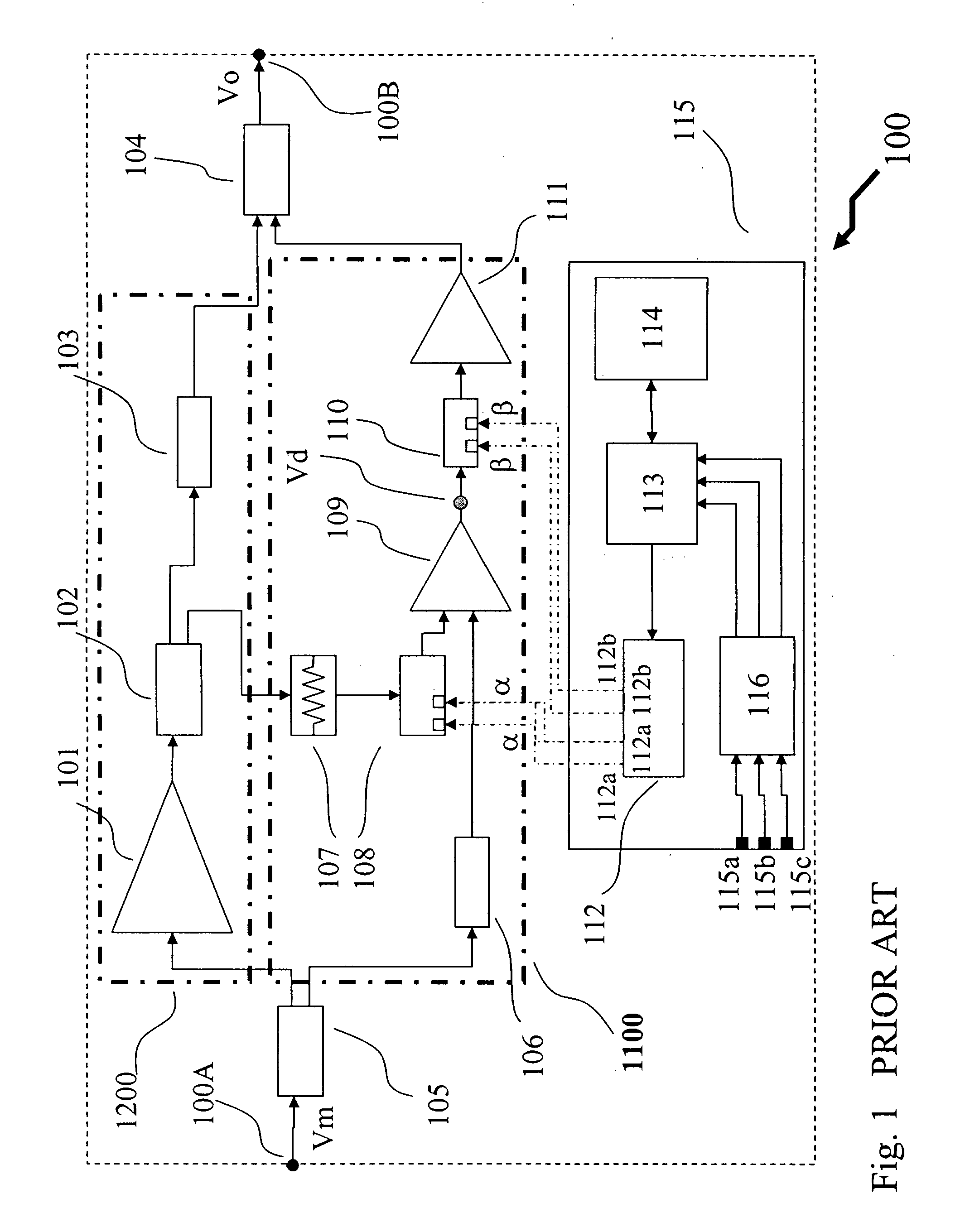
[0041]Shown in FIG. 1 is an exemplary feed-forward amplifier system 100 according to Chen et al (U.S. Pat. No. 5,963,091). The feed-forward amplifier system 100 providing the required amplification in the transmit path of a wireless WiMAX transceiver embedded into a portable device, for example. As shown the feed-forward distortion correction system 100 comprises an RF input port 100A which receives an RF modulated signal Vm which is to be amplified, and provided as an amplified linear replica at the output port 100B as amplified signal Vo.

[0042]The RF input port 100A is electrically coupled to input splitter 105 which taps a predetermined portion of the RF modulated signal Vm to feed forward into the correction signal path 1100, and couples the remaining RF modulated signal Vm into the main arm 1200. The main arm 1200 couples the RF modulated signal Vm from the input splitter 105 to the power amplifier 101 which amplifies the RF modulated signal Vm as required by the overall system...


PUM


Abstract

A method of reducing distortion in the output of an amplifier is provided. The method comprises subtractively combining baseband error signals with the appropriate phase shift with baseband input signals, the baseband error signals generated by subtractively combining delayed fed-forward portions of the baseband input signals with baseband converted portions of a fed-back amplified output signal, the amplified output signal being a distorted replica of combined up-converted baseband input signals. The baseband error signals being filtered prior to the combining function, and also providing inputs to a controller which adjusts active elements of the amplification and fed-back paths in order to minimize the distortion within the output of the amplifier.

Description

FIELD OF THE INVENTION[0001]The invention relates to microwave amplifiers, and more specifically to correcting distortion generated in microwave amplifiers.BACKGROUND OF THE INVENTION[0002]In recent years, advances in semiconductor integrated circuits for wireless and RF technology have dramatically changed our perceptions, use, and reliance upon portable electronic devices. The uses of wireless technology are widespread, increasing, and include, but are not limited to, telephony, Internet e-mail, Internet web browsers, global positioning, photography, diary, address book, and in-store navigation. Additionally, devices incorporating wireless technology have expanded to include not only cellular telephones, but Personal Data Analyzers (PDAs), laptop computers, palmtop computers, gaming consoles, printers, telephone headsets, portable music players, point of sale terminals, global positioning systems, inventory control systems, and even vending machines. Today, many of these devices a...

Claims


Application Information

Patent Timeline
Patent Type & Authority Applications(United States)
IPC IPC(8): H04B1/04
CPCH03F1/34H03F3/24H03F2200/336H03F2200/57
Inventor GRUNDLINGH, JOHANSMITH, HOWARD JAMESNISBET, JOHNRABJOHN, GORDON G.
Owner SIGE SEMICON
Why Eureka
Try Eureka