Imaging Apparatus for IR Four-Wave Mixing Polarization Microscopy

a polarization microscope and imaging apparatus technology, applied in the field of ir four-wave mixing polarization microscopes, can solve the problems of insufficient optical contrast between molecular chemical species, inability to selectively measure the spatial distribution of molecular chemical species, and difficulty in obtaining clear morphological images of various intracellular organs and materials in the sample, etc., to achieve serious lowering of spatial resolution

Inactive Publication Date: 2008-12-11
KOREA RES INST OF STANDARDS & SCI
View PDF8 Cites 39 Cited by
  • Summary
  • Abstract
  • Description
  • Claims
  • Application Information

AI Technical Summary

Benefits of technology

[0019]It is an object of the present invention to provide an imaging apparatus for IR four-wave mixing polarization microscopy, which uses molecular vibrational resonance of IR laser and overcomes the problem that the spatial resolution is seriously lowered by the diffraction limit, when detecting an inherent molecular vibration of materials in a sample without staining the sample or adding fluorescent markers.

Problems solved by technology

In observing an optically transparent micro-sample including a bio-sample like cells and tissues under a general optical microscope, there are some problems that it is very difficult to obtain a clear morphological image of various intracellular organs and materials in the sample and also it is impossible to selectively measure a spatial distribution of molecular chemical species.
This is because a difference between objects and a background substance is minute in optical properties and thus a sufficient optical contrast therebetween is not provided.
In other words, it is not easy to distinguish the specific micro-structures or micro-materials to be observed from the background substance in the sample.
However, since the fluorescent marker as an exogenous material is added in the bio-sample, there is a basic problem that an original status of the bio-sample is not maintained as it was.
Because the added exogenous material lowers activity of the bio-sample, it is difficult to obtain exact information about the behavior of the bio material.
Furthermore, since a coloring matter of the fluorescent marker is easily photobleached even by very weak lasers, it is also difficult to observe the image continuously or in time-lapse measurements.
However, in the mid-IR regime with wavelength range of 2.5˜18 μm where light is resonated with the molecular vibration and thus strongly absorbed, it is in practice very difficult to realize a wavelength-tunable laser beam source which is required for the microscopic image.
Furthermore, due to the limitation imposed by diffraction phenomenon, the infrared absorption microscope has a very low spatial resolution of 10˜40 μm compared with the spatial resolution (of 0.3˜0.5 μm) in an optical microscope with a visible beam source.
However, it has also a disadvantage that it takes a long time to obtain an image because the intensity of Raman signal for providing spectroscopic information is very weak.
Particularly, in the case that a dynamic characteristic of the living bio-sample is observed, or an intensity of excitation laser cannot be sufficiently increased to avoid damage to the sample, the disadvantage becomes further serious.
However, in order to obtain the microscopic image, it is necessary for a surface of the sample to be mechanically scanned with high precision relative to the tips of the optical fiber, but it is difficult to quickly obtain the image since the aperture has a very low transmission efficiency (˜10−6) at IR wavelengths.
In addition, with a current technical standard, it is difficult to provide a reliable process technology which manufactures the optical fiber for efficiently transferring the IR.
However, the CARS microscope has also some disadvantages that the molecular selectivity and the signal-to-noise ratio are lowered by the non-resonant third-order nonlinear optical susceptibility which is not relevant to the natural vibration of molecules, and the measurement sensitivity is still low in comparison with a method using direct resonance absorption in the mid-IR range.

Method used


Image

  • Imaging Apparatus for IR Four-Wave Mixing Polarization Microscopy
  • Imaging Apparatus for IR Four-Wave Mixing Polarization Microscopy
  • Imaging Apparatus for IR Four-Wave Mixing Polarization Microscopy

Examples


Embodiment Construction

[0037]

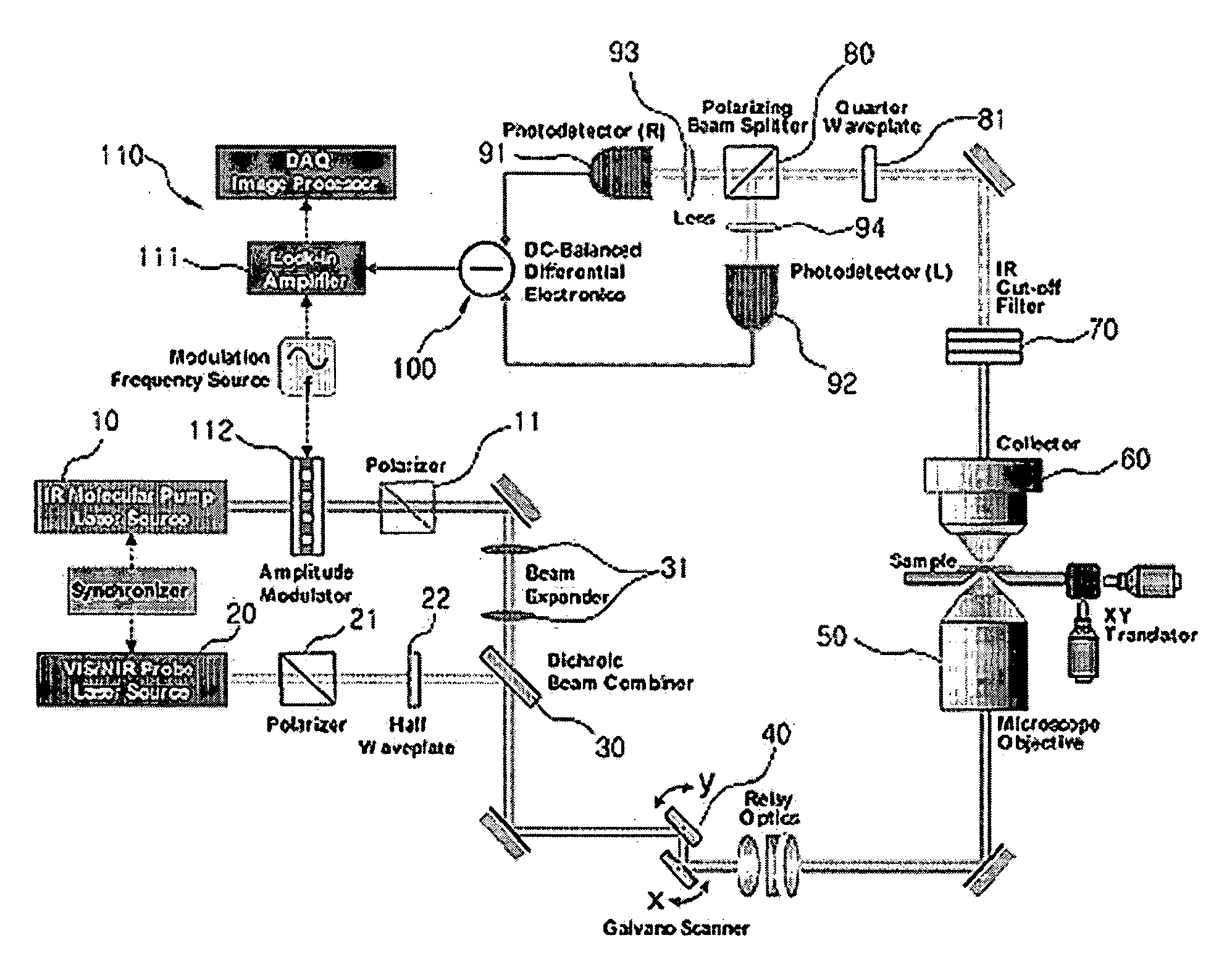
10: pump beam source20: probe beam source11, 21: polarizer30: beam combiner40: scanner50: optical focusing system60: collecting optical system70: dichroic beam splitter80: polarizing beam splitter91, 92: photodetector100: polarization differential detector110: data analyzer

Best Mode for Carrying Out the Invention

[0038]Practical and presently preferred embodiments of the present invention are illustrated as shown in the following Examples and Comparative Examples.

[0039]However, it will be appreciated that those skilled in the art, on consideration of this disclosure, may make modifications and improvements within the spirit and scope of the present invention.

[0040]FIG. 4 is a diagram of laser-sample interaction energy level and transition which are proposed by an IR four-wave mixing polarization differential detection according the present invention.

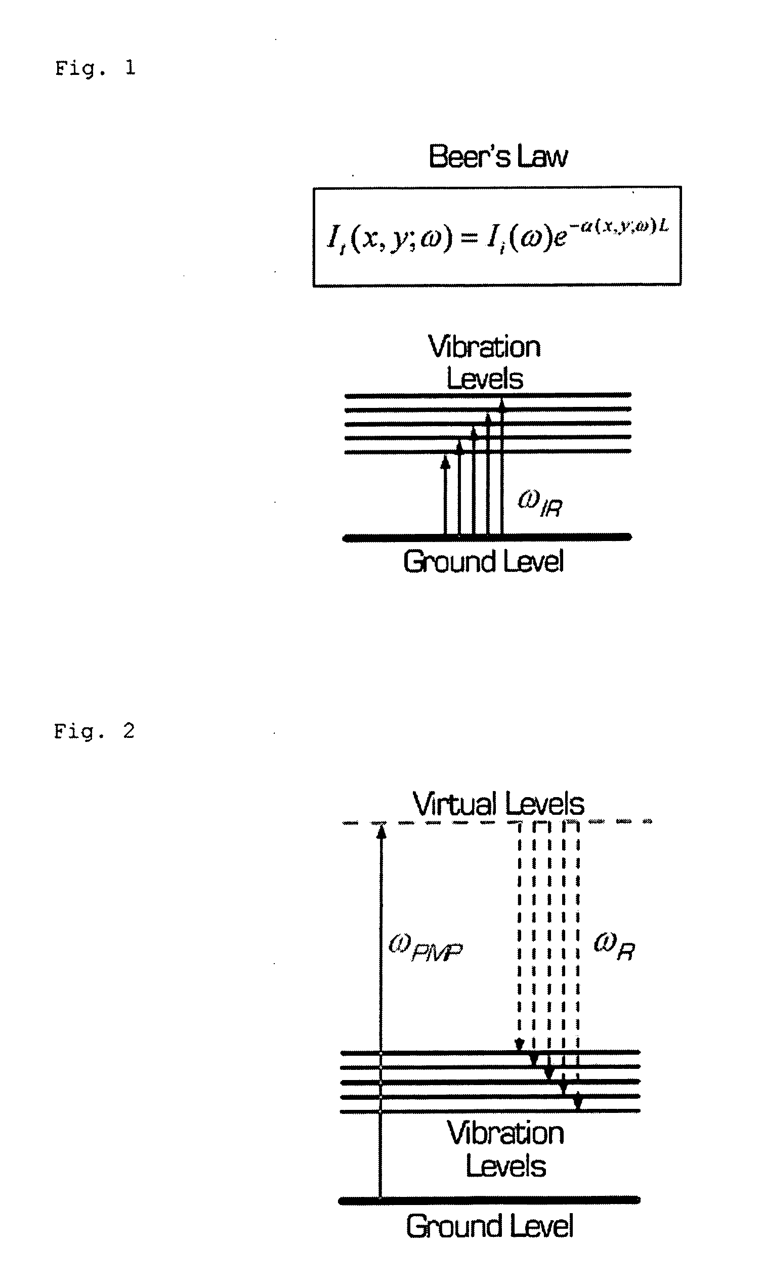
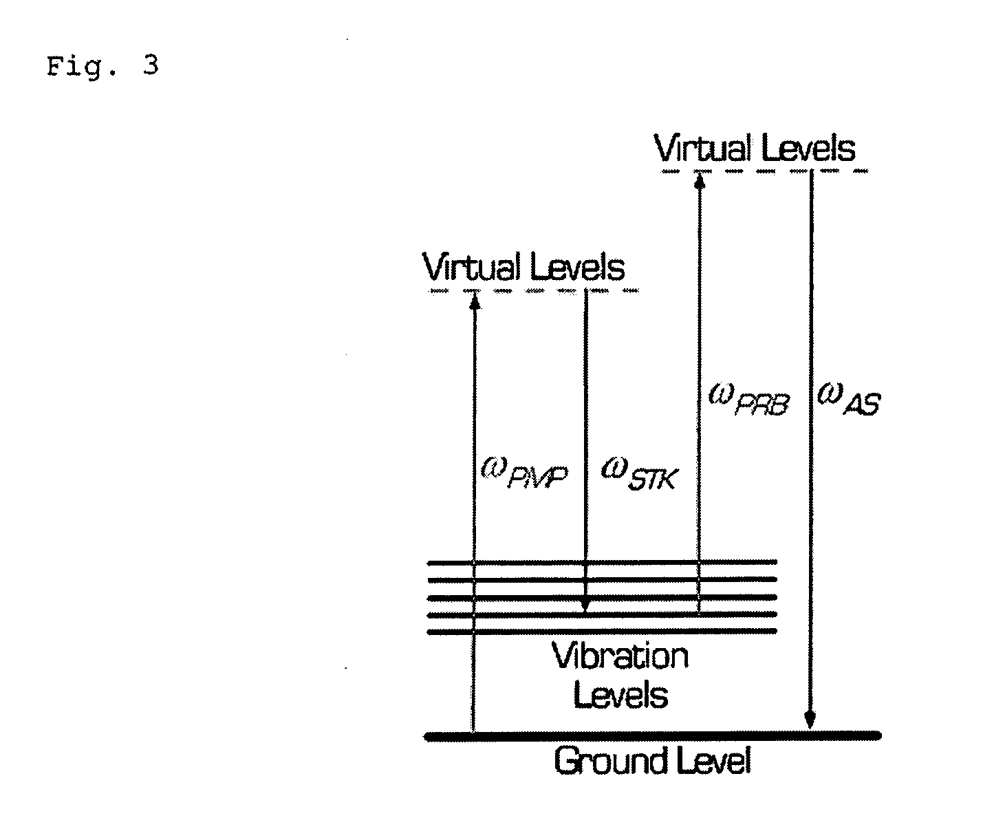
[0041]In obtaining a selective spectroscopic signal with respect to a certain molecular vibration, if a laser having a frequency ω...


PUM


Abstract

The present invention relates to an imaging apparatus for IR four-wave mixing polarization microscopy. The imaging apparatus comprises a pump beam source for generating an infrared pump beam; a probe beam source for generating a probe beam (search beam); a polarizer for linearly polarizing the pump beam and probe beam; a beam combiner which synchronizes temporally and overlaps spatially the polarized pump beam and probe beam on the same axis; a scanner for two-dimensionally scanning the combined pump beam and probe beam; an optical focusing system for focusing the scanned pump beam and probe beam on a local point of the sample; a collecting optical system for collecting the beam which is formed by that the focused beams are interacted with the sample and of which phase is anisotropically retarded by nonlinear birefringence of the sample and forming a parallel beam; a dichroic beam splitter for removing the infrared pump beam out of the parallel beam and splitting the probe beam of which phase is anisotropically retarded; a polarizing beam splitter for converting the split and ansotripically phase-retarded probe beam into linerly polarized beams having their axes perpendicular to each other; a photodetector for detecting an intensity of each of the converted linerly polarized beams; a polarization differential detector for detecting a polarization difference based on the detected intensities of the linerly polarized beams; and a data analyzer for acquiring the detected polarization difference signal and extracting a spectrospcopic information corresponding to the strength of molecular vibrational coherence of the sample.

Description

TECHNICAL FIELD[0001]The present invention relates to an IR four-wave mixing polarization microscope and a method thereof, more particularly, to a technology for obtaining a molecular vibrational microscopic image using a polarization-dependent nonlinear spectroscopic signal obtained by focusing and spatial scanning of multi-wavelength laser beams in a sample.BACKGROUND ART[0002]In observing an optically transparent micro-sample including a bio-sample like cells and tissues under a general optical microscope, there are some problems that it is very difficult to obtain a clear morphological image of various intracellular organs and materials in the sample and also it is impossible to selectively measure a spatial distribution of molecular chemical species. This is because a difference between objects and a background substance is minute in optical properties and thus a sufficient optical contrast therebetween is not provided. In other words, it is not easy to distinguish the specific...

Claims


Application Information

Patent Timeline
Patent Type & Authority Applications(United States)
IPC IPC(8): G01J3/00
CPCG01J3/433G01N21/21G01N21/23G01N21/636G02B21/0064
Inventor LEE, JAE YONGLEE, EUN SEONG
Owner KOREA RES INST OF STANDARDS & SCI
Why Eureka
Try Eureka