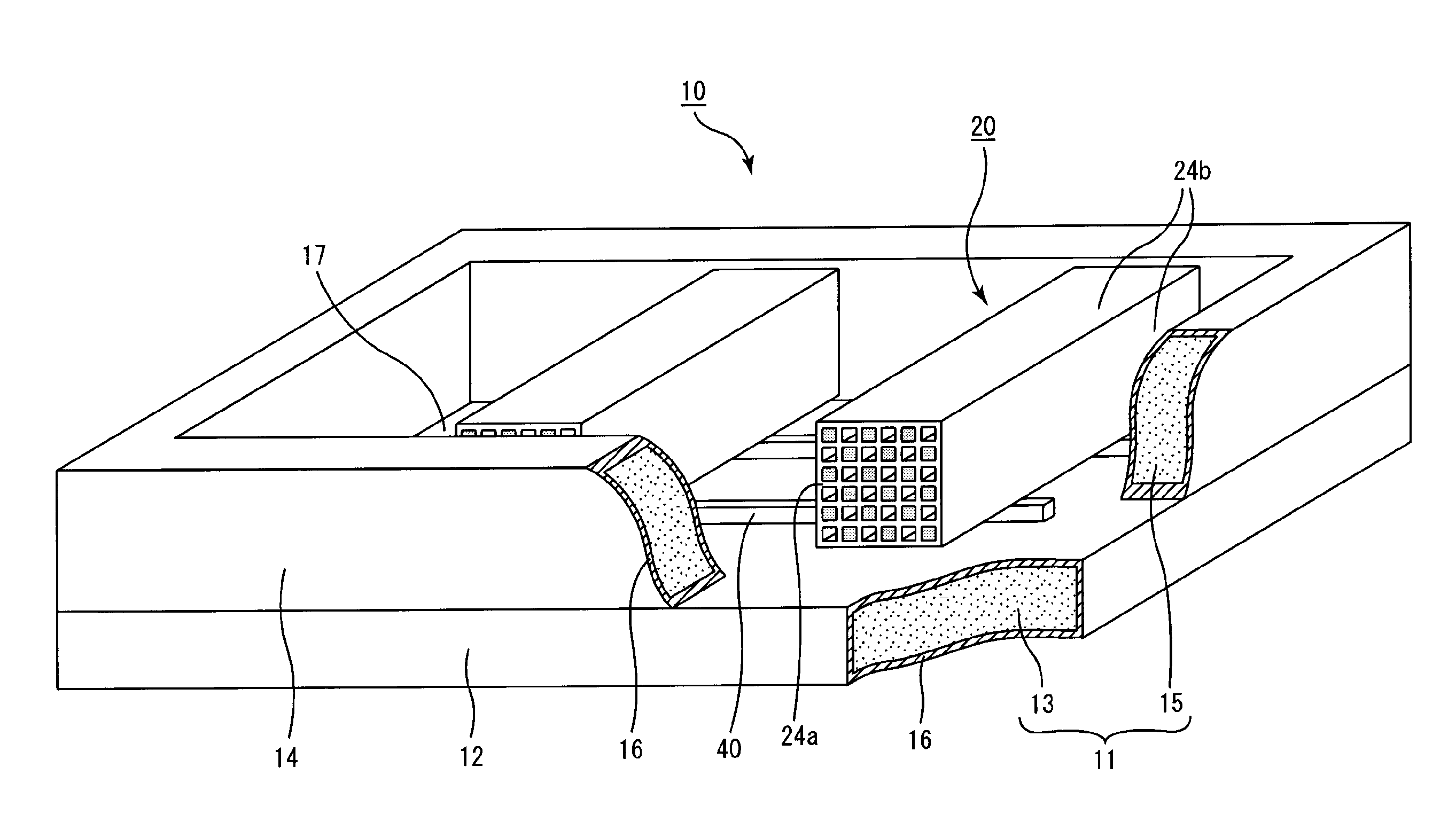
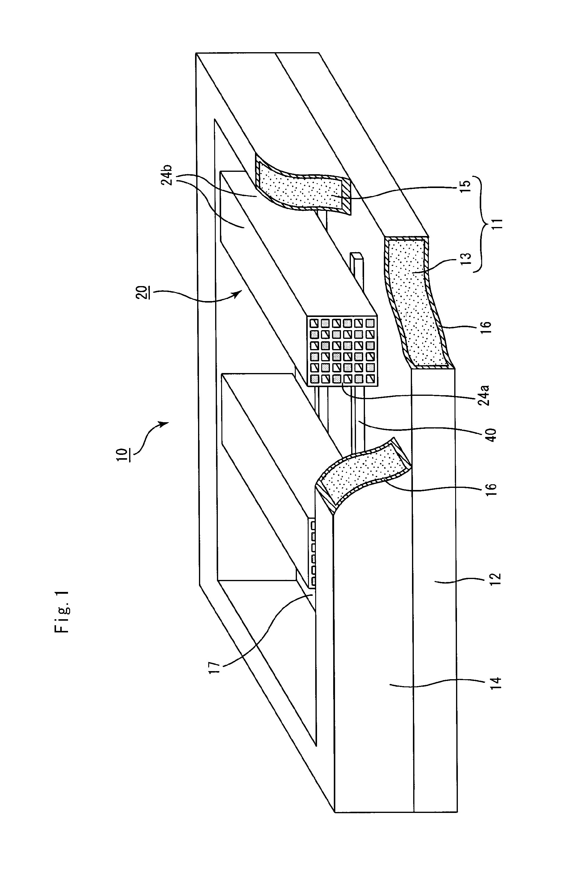
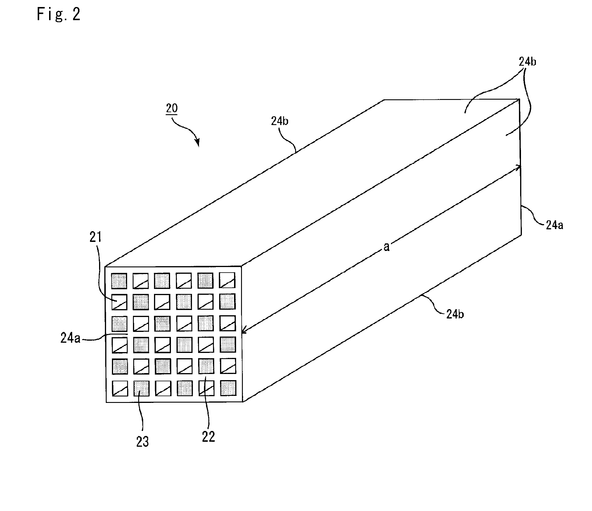
[0043]In addition, in the method for manufacturing a
honeycomb structure according to the embodiments of the present invention, since the
surface roughness of the coat layer is about 10 μm or less, irregularities due to the irregularities of the coat layer are less likely to occur on the surface of the honeycomb fired body even if the honeycomb molded body is fired while being placed in the firing jig. Therefore, in the
honeycomb structure using the obtained honeycomb fired body, since
cell cracks, decrease of strength, and the like due to such fine irregularities tend not to occur, it may be easier to prevent the loss of the product (low production yield) from occurring and to keep the qualities of the product for a long time.
[0044]Moreover, in the method for manufacturing a honeycomb structure according to the embodiments of the present invention, since the
surface roughness of the coat layer is about 10 μm or less, stress due to fine irregularities tends not to be generated. Therefore, since cracks or fractures tend not to occur on the surface of the coat layer, it may be easier to stably use the firing jig for a long time. Also, since it is possible to use the firing jig for a long time, the running costs for firing may be
cut down more easily.
[0045]In the method for manufacturing a honeycomb structure according to the embodiments of the present invention, since a dense coat layer is formed by a vapor-
phase method, it is may be easier to increase strength of the coat layer, and by extension to increase durability as a firing jig.
[0046]Also, since it is possible to form such a coat layer on the housing body through a single operation, it may be easier to shorten a time period for stabilization of the coat layer, and thus the firing conditions may be more easily stabilized quickly. Therefore, it is possible to shorten the time period for manufacturing a honeycomb structure including preparation.
[0047]In the method for manufacturing a honeycomb structure according to the embodiments of the present invention, since a
chemical vapor infiltration method is employed as the vapor-
phase method, it is possible to form a coat layer having high purity of SiC. Thus, reactions that are not required for the formation of the sintered body due to the impurities and the like tend to be prevented as much as possible, and a honeycomb structure having high qualities may be manufactured more easily.
[0043]In addition, in the method for manufacturing a honeycomb structure according to the embodiments of the present invention, since the
surface roughness of the coat layer is about 10 μm or less, irregularities due to the irregularities of the coat layer are less likely to occur on the surface of the honeycomb fired body even if the honeycomb molded body is fired while being placed in the firing jig. Therefore, in the honeycomb structure using the obtained honeycomb fired body, since
cell cracks, decrease of strength, and the like due to such fine irregularities tend not to occur, it may be easier to prevent the loss of the product (low production yield) from occurring and to keep the qualities of the product for a long time.
[0050]In the method for manufacturing a honeycomb structure according to the embodiments of the present invention, since the honeycomb molded body is placed in the firing jig by interposing a spacer including carbon, it may be easier to sufficiently supply C in the reactions shown in the
chemical reaction equations (1) and (3), and to sufficiently proceed the formation of the sintered body.
[0051]Here, residual portion of
organic content included in the
raw material composition after
degreasing is a supply source of C in the reactions shown in the
chemical reaction equations (1) and (3), but since an amount of the residual content is very small, the residual content finally runs out as the formation of the sintered body proceeds. Even in such a case, by using the spacer including carbon, the reactions shown in the
chemical reaction equations (1) and (3) proceed by using this carbon as the supply source, so that it is possible to proceed the
sintering of the
silicon carbide particles.
[0052]The method for manufacturing a honeycomb structure according to the embodiments of the present invention includes
degreasing the honeycomb molded body by use of the predetermined firing jig, while the honeycomb molded body is placed in the firing jig; and firing the honeycomb molded body, while the degreased honeycomb molded body is placed in the firing jig. Thus, it is not required to transport the honeycomb molded body to the firing jig after the
degreasing of the honeycomb molded body. Here, since the degreased honeycomb molded body has a low
water content and is not sintered, the degreased honeycomb molded body is fragile and hard to
handle; however, since the honeycomb molded body can be fired without being transported after the degreasing, it may be easier to prevent damages of the honeycomb molded body due to the transportation to the firing jig.
[0053]Moreover, since space is formed between the honeycomb molded body and the placing face of the housing body by placing the honeycomb molded body in the housing body by interposing the spacer, it may be easier to make an
atmosphere around the honeycomb molded body more uniform. Thus, it may be easier to prevent variations in the state of proceeding of the degreasing depending on the part of the honeycomb molded body from occurring.
[0054]Moreover, since the honeycomb molded body is allowed not to contact the firing jig by using the spacer upon being placed, it may be easier to prevent problems such as insufficient strength due to uneven firing of the
cell wall forming the side face of the honeycomb molded body, recesses, breakages of the
cell wall, and cracks due to a contact with the firing jig, and the like. Also in the case of using the spacer in place of placing the honeycomb molded body directly, it may be easier to alternatively obtain the effect of suppressing the influence of the irregularities on the surface of the coat layer of the firing jig.
[0056]As in the method for manufacturing a honeycomb structure according to the embodiments of the present invention, a dense layer having a surface roughness of a predetermined value is to be obtained even in the case of forming the coat layer by
grinding the SiC coat layer including the forming material of the SiC coat layer. Therefore, since it may be easier to prevent peelings, cracks, and irregularities from occurring, irregularities or the like tend not to occur on the surface of a honeycomb fired body to be obtained. By extension, it may be easier to manufacture a honeycomb structure having a predetermined quality.
[0039]In the firing jig according to the embodiments of the present invention, the
polymer mainly containing hydridopolycarbosilane, the mixture containing SiC particles and SiO2 particles, the material containing SiC particles with SiO2 film formed on a surface of the particles, or the mixture containing Si and C may be used as the forming material of the SiC coat layer. In the case of using the material of this kind, the SiC coat layer is to be coarsely formed in the vicinity of the surface, and densely formed inside. Since the coarsely-formed surface portion is ground so as to allow the densely-formed portion to emerge on the surface of the SiC coat layer of this kind, it may be easier to prevent peelings, cracks, and the like from occurring after
grinding.


