Anode and battery

a technology applied in the field of anode and battery, can solve the problems of easy decline in cycle characteristics and easy decline in manufacturing yield of secondary batteries, and achieve the effects of improving performance, improving efficiency and reducing production costs

Active Publication Date: 2008-12-11
MURATA MFG CO LTD
View PDF7 Cites 37 Cited by
  • Summary
  • Abstract
  • Description
  • Claims
  • Application Information

AI Technical Summary

Benefits of technology

[0011]As recent portable electronic devices have a smaller size, higher performance and more functions, secondary batteries are frequently charged and discharged accordingly, thereby cycle characteristics easily decline. Moreover, in the case where silicon is used as an anode active material to increase the capacity of a secondary battery, the anode active material is easily swelled during charge and discharge, so the manufacturing yield of the secondary battery easily declines. Therefore, further improvement in the cycle characteristics and the manufacturing yield is desired.
[0012]In view of the foregoing, it is desirable to provide an anode and a battery which are capable of improving cycle characteristics and a manufacturing yield.
[0016]In the anode according to the embodiment of the invention, the anode active material includes a plurality of pores, and the rate of change in the amount of mercury intruded into the plurality of pores which is measured by mercury porosimetry is distributed so as to have a peak in a diameter range from 80 nm to 1200 nm both inclusive, so compared to the case where the rate of change is not distributed so as to have a peak in the diameter range, even in the case where the anode active material has high activity, the anode active material is resistant to reacting with another material, and even in the case where the anode active material is easily swelled during electrode reaction, the anode is resistant to deformation. Thereby, in a battery including the anode according to the embodiment of the invention, the cycle characteristics and the manufacturing yield may be improved. In this case, when the peak is included in a diameter range form 100 nm to 1000 nm both inclusive, more specifically in a diameter range from 120 nm to 600 nm both inclusive, a higher effect may be obtained.
[0017]Moreover, when the anode active material includes oxygen, and the oxygen content in the anode active material is within a range from 3 at % to 40 at % both inclusive, or when the anode active material includes at least one kind of metal element selected from the group consisting of iron, cobalt, nickel, titanium, chromium and molybdenum, or when the anode active material includes an oxygen-containing region (a region in which oxygen is included and the oxygen content is higher than that in a region other than the region) in its thickness direction, a higher effect may be obtained.
[0018]Further, when the ten-point height of roughness profile Rz of the surface of the anode current collector is within a range from 1.5 μm to 6.5 μm both inclusive, a higher effect may be obtained.

Problems solved by technology

As recent portable electronic devices have a smaller size, higher performance and more functions, secondary batteries are frequently charged and discharged accordingly, thereby cycle characteristics easily decline.
Moreover, in the case where silicon is used as an anode active material to increase the capacity of a secondary battery, the anode active material is easily swelled during charge and discharge, so the manufacturing yield of the secondary battery easily declines.

Method used


Image

  • Anode and battery
  • Anode and battery
  • Anode and battery

Examples


example 1-1

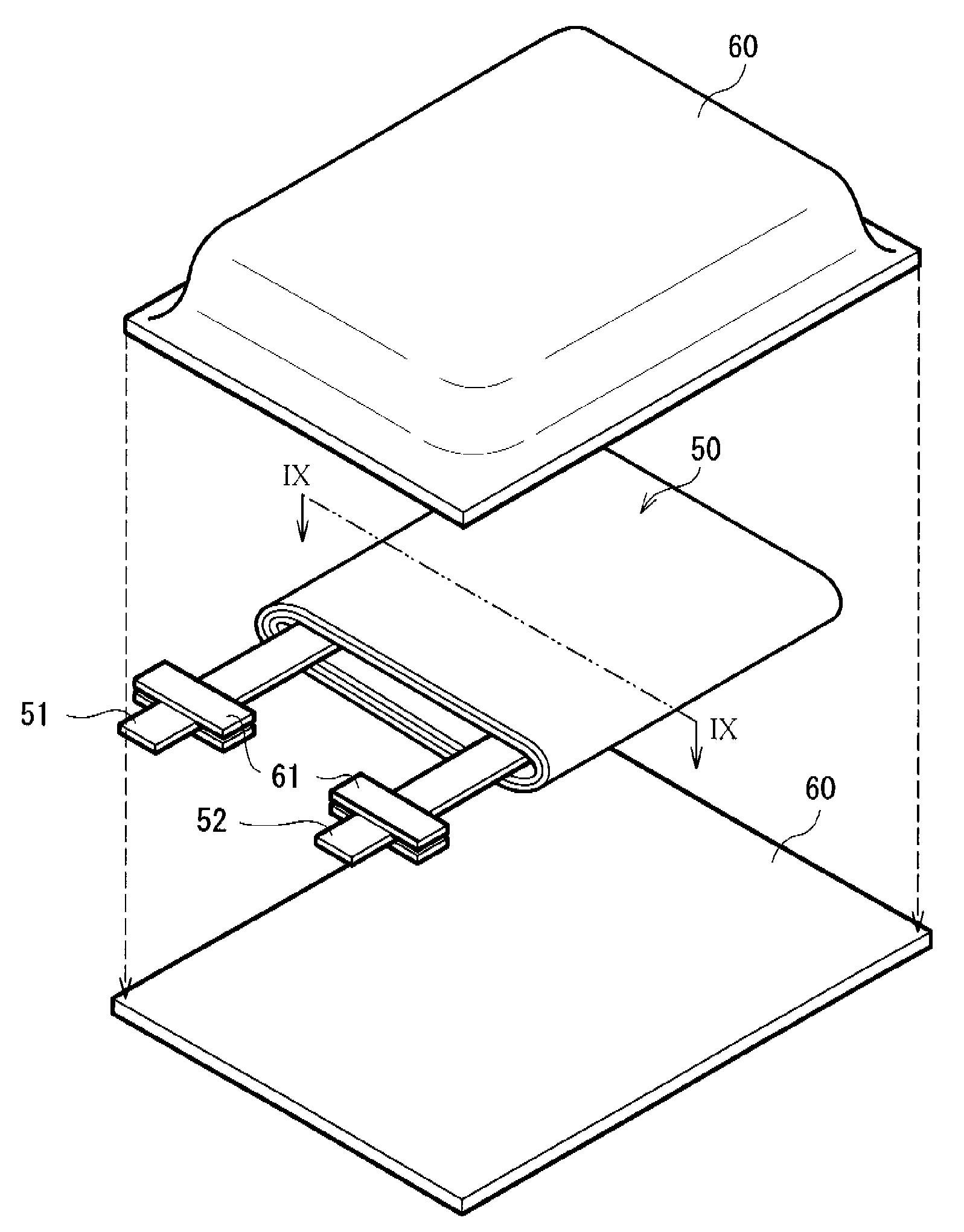
[0133]A laminate film type secondary battery shown in FIGS. 8 and 9 was manufactured by the following steps. At that time, the laminate film type secondary battery was a lithium-ion secondary battery in which the capacity of the anode 54 is represented based on insertion and extraction of lithium.

[0134]At first, the cathode 53 was formed. After lithium carbonate (Li2CO3) and cobalt carbonate (CoCO3) were mixed at a molar ratio of 0.5:1, the mixture was fired in air at 900° C. for 5 hours to obtain a lithium-cobalt complex oxide (LiCoO2). Next, after 91 parts by weight of the lithium-cobalt complex oxide as a cathode active material, 6 parts by weight of graphite as an electrical conductor and 3 parts by weight of polyvinylidene fluoride as a binder were mixed to form a cathode mixture, the cathode mixture was dispersed in N-methyl-2-pyrrolidone to form paste-form cathode mixture slurry. Finally, after the cathode mixture slurry was uniformly applied to both sides of the cathode curr...

examples 1-2 to 1-12

[0139]Secondary batteries were formed by the same steps as those in Example 1-1, except that instead of 80 nm, the peak diameter was 100 nm (Example 1-2), 120 nm (Example 1-3), 150 nm (Example 1-4), 200 nm (Example 1-6), 300 nm (Example 1-6), 400 nm (Example 1-7), 500 nm (Example 1-8), 600 nm (Example 1-9), 800 nm (Example 1-10), 1000 nm (Example 1-11) or 1200 nm (Example 1-12).

examples 2-1 to 2-12

[0147]Secondary batteries were formed by the same steps as those in Examples 1-1 to 1-12, except that the anode active material had a six-layer configuration. In the case where the anode active material was formed, while the anode current collector 54A was moved back and forth relatively to an evaporation source at a deposition rate of 100 nm / s, silicon was deposited successively to be laminated.


PUM

PropertyMeasurementUnit
diameteraaaaaaaaaa
diameteraaaaaaaaaa
diameteraaaaaaaaaa

Abstract

A battery capable of improving cycle characteristics and a manufacturing yield is provided. An anode includes: an anode current collector; and an anode active material layer arranged on the anode current collector, in which the anode active material layer includes an anode active material including a plurality of pores, and the rate of change in the amount of mercury intruded into the plurality of pores is distributed so as to have a peak in a diameter range from 80 nm to 1200 nm both inclusive, the amount of mercury intruded being measured by mercury porosimetry.

Description

CROSS REFERENCES TO RELATED APPLICATIONS[0001]The present invention contains subject matter related to Japanese Patent Application JP 2007-149251 filed in the Japanese Patent Office on Jun. 5, 2007, the entire contents of which being incorporated herein by reference.BACKGROUND OF THE INVENTION[0002]1. Field of the Invention[0003]The present invention relates to an anode including an anode current collector and an anode active material layer arranged on the anode current collector, and a battery including the anode.[0004]2. Description of the Related Art[0005]In recent years, portable electronic devices such as camera-integrated VTRs (videotape recorders), cellular phones, or laptop computers are widely used, and size and weight reduction in the portable electronic devices and an increase in longevity of the portable electronic devices have been strongly demanded. Accordingly, as power sources for the portable electronic devices, the development of batteries, specifically lightweight...

Claims


Application Information

Patent Timeline
Patent Type & Authority Applications(United States)
IPC IPC(8): H01M2/02H01M4/02H01M4/00H01M6/04H01M4/13H01M4/48H01M4/62H01M4/70H01M10/052H01M10/0566H01M10/0567H01M10/0568H01M10/0569H01M50/119H01M50/121H01M50/129H01M50/133
CPCH01M2/0285H01M4/134H01M4/364H01M4/366H01M4/38H01M4/483H01M4/64H01M10/052H01M10/0568H01M10/0569H01M2004/021Y02E60/122H01M4/386Y02E60/10H01M50/133H01M50/121H01M50/129H01M50/119H01M4/02
Inventor HIROSE, TAKAKAZUKAWASE, KENICHIKONISHIIKE, ISAMUKURASAWA, SHUNSUKEIWAMA, MASAYUKIMATSUMOTO, KOICHI
Owner MURATA MFG CO LTD
Why Eureka
Try Eureka