
Method of forming thin metal film and thin metal film manufactured by the forming method

Inactive Publication Date: 2008-12-18
PANASONIC CORP
View PDF3 Cites 3 Cited by
  • Summary
  • Abstract
  • Description
  • Claims
  • Application Information

AI Technical Summary

Benefits of technology

[0007]The present invention has been achieved in view of the above and it intends to provide a method of forming a metal film in which the metal film using fine metal particles on a smooth substrate is less peeled from the substrate, as well as a metal film prepared by the forming method. Further, the invention intends to provide a method of forming a metal film having good adhesion in which metal wirings are not peeled from a substrate even by a plating pretreatment or a chemical treatment with a plating solution upon forming a thin metal plating film on the metal wirings formed on the substrate for increasing the conductivity, as well as a metal film prepared by the forming method.
[0009]The present invention can provide a method of forming a metal film capable of forming a metal film layer having good adhesion in which the metal film layer is not peeled from a substrate even by a plating pretreatment or chemical treatment with a plating solution upon forming a metal plating film on a metal film layer for increasing the conductivity.

Problems solved by technology

However, even if the silane coupling agent is used, when baking is conducted at a temperature of 250° C. or higher and 300° C. or lower, the coupling agent is decomposed into silicon oxide and while this has close adhesion with a smooth substrate, sufficient adhesion cannot be obtained for a thin metal film using fine particles of a noble metal such as Ag or Au with the silicon oxide to result in a problem that metal wirings are peeled from a substrate, particularly, in a case of forming a metal plating film on thin metal wirings for increasing the conductivity, by a plating pretreatment or chemical treatment with a plating solution.
Further, while there has been a method of forming unevenness on the surface of a smooth substrate by using chemicals or physical means and ensuring adhesion by an anchoring effect, this also resulted in a problem that no sufficient highly fine pattern can be obtained due to the presence of the physical unevenness on the surface of the substrate.

Method used


Image

  • Method of forming thin metal film and thin metal film manufactured by the forming method
  • Method of forming thin metal film and thin metal film manufactured by the forming method
  • Method of forming thin metal film and thin metal film manufactured by the forming method

Examples


embodiment 1

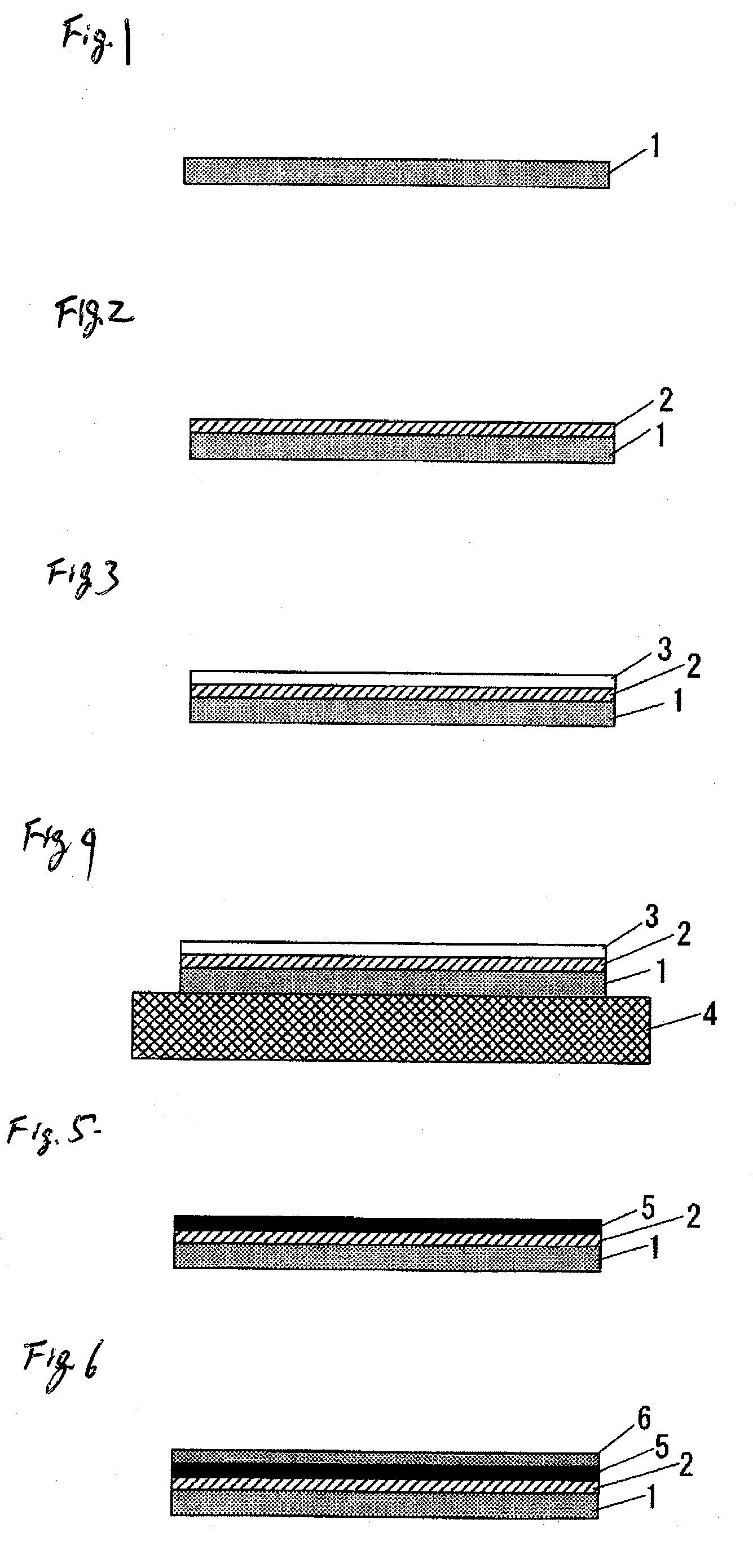
[0023]FIG. 1 to FIG. 6 are views showing an example of a procedure for the method of forming a thin metal film according to Embodiment 1 of the invention. At first, as shown in FIG. 1, an inorganic oxide substrate 1 is provided. The material used for the inorganic oxide substrate 1 includes, for example, quartz glass, non-alkali glass, borosilicate glass, sapphire glass, alumina, and zirconia.

[0024]Then, as shown in FIG. 2, an under-layer 2 is formed over the entire surface of the inorganic oxide substrate 1 for improving an adhesion strength of a thin metal film layer 5 to be formed in the subsequent step to the inorganic oxide substrates 1.

[0025]The material for the under-layer 2 includes metals and metal oxides having affinity both with the thin metal film layer 5 comprising noble metal such as silver or gold and the inorganic oxide substrate 1 such as of glass. In this case, the metal can improve the adhesion with the thin metal film layer 5 by forming a diffusion layer with the...

embodiment 2

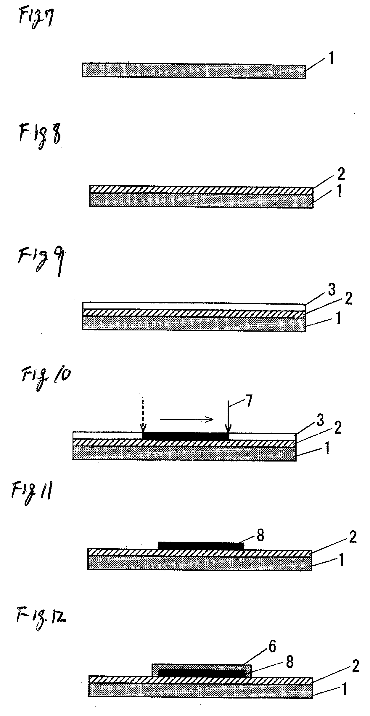
[0036]FIG. 7 to FIG. 12 are views showing an example of procedures for the method of forming a thin metal film according to Embodiment 2 of the invention. At first, in the same manner as the treatment shown in FIG. 1 to FIG. 3 for Embodiment 1, a coupling agent is coated over the entire surface on the inorganic oxide substrate 1 to form an under-layer 2, a ultra-fine metal particle layer 3 is formed over the entire surface on the under-layer 2, and then they are air dried (FIG. 7 to FIG. 9).

[0037]Then, as shown in FIG. 10, a laser light as heating means 7 is irradiated on the micro-fine metal particles layer 3 so as to form a predetermined pattern. Since this applies heat to a portion of the micro-fine particle layer 3 irradiated with the laser light, the micro-fine metal particle layer 3 at that portion is transformed into a thin metal film layer 5, whereas the micro-fine metal particle layer 3 at a position not irradiated by the laser light is not metallized but remains as it is. ...

example 1

[0042]A thin metal film was formed by the method shown in FIG. 1 to FIG. 6 for Embodiment 1 described above. A 2-butanol solution of tetra-n-butyl titanate (ORGATIX TA-25 (trade name of products) manufactured by Matsumoto Chemical Industry Co., Ltd.) was prepared and an under-layer 2 was formed on a previously cleaned glass substrate as an inorganic oxide substrate 1 by a dipping method (pull-up speed: 25 mm / min) and air-dried. A fine particle silver ink dispersed in toluene (Ag1T (trade name of products), manufactured by ULVAC Materials, Inc.) was coated by a spin coating method and air dried to form a micro-fine metal particle layer 3 on the glass substrate. Then, for metallizing the micro-fine metal particles, it was heated by a hot plate as the heating device 4 at 300° C. for 2 min to obtain a thin silver film as a thin metal film layer 5 of 0.1 μm.

[0043]After cleaning the obtained thin silver film by a pretreatment step of alkali degreasing and acid activation, a copper plating...


PUM

PropertyMeasurementUnit
Temperatureaaaaaaaaaa

Abstract

An under-layer 2 comprising a coupling agent having a metal element to be transformed to an oxide is disposed on the surface of an inorganic oxide substrate 1, and a liquid containing micro-fine metal particles dispersed therein is coated on the under-layer 2 to form a micro-fine metal particle layer 3. Then, temperature is elevated to a metallizing temperature of the micro-fine metal particles, to form a thin metal film layer 5.

Description

BACKGROUND[0001]1. Field of the Invention[0002]The present invention concerns a forming method of keeping goods adhesion between a thin metal film and a substrate, and a thin metal film prepared by the forming method.[0003]2. Description of the Related Art[0004]In recent years, micro-fine metal particles mixed and dispersed to an organic solvent and a resin into a paste have high fluidity like an ink and can form a thin metal film by a simple and convenient method of merely coating and baking on a substrate. A synthesis method of micro-fine metal particles is generally classified into three methods that are a solid phase method, a liquid phase method, and a gas phase method. Among them, since the solid phase method including pulverization has a limit in fine particulation, the liquid phase method and the gas phase method are suitable to the synthesis of micro-fine particles. An in-gas evaporation method as a typical gas phase method is a method of heat melting a metal and evaporatin...

Claims


Application Information

Patent Timeline
IPC IPC(8): B32B15/00B05D3/02
CPCC03C17/002C03C17/36C03C17/3607C03C17/3618C03C17/3644C03C17/3649C03C17/3689C03C17/3697C03C2218/11C03C2218/328C23C18/08C23C18/1216C23C18/14C23C18/143
Inventor TANAKA, HISAHIRONOTOHARA, YASUHIROYATSUNAMI, RYUICHIMIYANISHI, SATORU
Owner PANASONIC CORP
Learn More