Method and Device for Characterising a Structure by Wavelength Effect in a Photoacoustic System

Active Publication Date: 2008-12-25
CENT NAT DE LA RECHERCHE SCI
View PDF20 Cites 13 Cited by
  • Summary
  • Abstract
  • Description
  • Claims
  • Application Information

AI Technical Summary

Benefits of technology

[0003]In the prior art, known U.S. Pat. No. 5,748,318 describes a system for the characterization of thin films and interfaces between thin films through measurements of their mechanical and thermal properties. In the system described, light is absorbed in a thin film or in a structure made up of several thin films, and the change in optical transmission or reflection is measured and analyzed. The change in transmission or reflection is used to supply information on the ultrasonic waves generated in the structure. In that way, it is possible to determine the thicknesses of the layers and various optical properties of the structure.
[0005]In order to increase the number of extracted characteristics, and in particular both the speed and the thickness, the publication entitled “Evidence of Laser-Wavelength Effect in Picosecond Ultrasonics: Possible Connection with Interband Transition” (Physics Review Letters, Mar. 12, 2001, Volume 86, Issue 12) describes the use of a pump-probe device as described above, but associated with a wavelength-tunable laser, thereby making it possible to cause the wavelength of the emitted signals to vary. By means of such wavelength effects, it is then possible to determine both thickness characteristics and speed characteristics for certain types of structure. As described in the publication entitled “A Novel Approach Using Picosecond Ultrasonics at Variable Laser-Wavelength for the Characterization of Aluminium Nitride Films Used for Microsystem Applications” (A. Devos, G. Caruyer, C. Zinck, and P. Ancey), World Congress on Ultrasonics (Paris Sep. 7-10, 2003), pp. 793-796 ISBN 2-9521105-0-6), for a structure that is transparent to the probe beam, an acousto-optical interaction appears in the material that causes oscillations to appear instead of mere pulses observed by echo. Such oscillations, referred to as “Brillouin” oscillations have a period dependent on the wavelength of the probe and on the speed of sound in the material. They are shown in FIG. 3 for two samples of SiN / Al / Si and SiO2 / Al / Si. In that example, it can be understood that the materials and the thicknesses distinguish the two samples from each other so that the Brillouin oscillations do not have the same period at the same wavelength for the probe signal (430 nm). The person skilled in the art can understood that measuring the period of the Brillouin oscillations gives information on the speed of sound in the material, independently of the thickness of the layer. When the acoustic wave reaches the free surface, it reflects off it by changing the sign of the deformation. This results in a jump in reflectivity appearing. The acoustic wave generated in depth by the “pump” beam carries a minute change in the thickness of the layer whose sign changes on reflection. This change is detected optically because the transparent layer then acts as a Fabry-Perot interferometer, as shown in the publication entitled “Ultrafast Vibration and Laser Acoustics in Thin Transparent Films”, O. B. Wright and T. L Hyoguchi, Optics Letters, Vol. 16, page 1529 (1991).
[0007]An object of the present invention is to reduce further the error rate on the measured data, while keeping the possibility of determining both thickness and speed values. The present invention thus intends to solve those prior art drawbacks by using, in particular, wavelength effects, e.g. by means of a tunable laser. To this end, the present invention is of the type described above and it is remarkable, in its broadest acceptation, in that it provides a device for characterizing a structure, said device comprising radiation generator means for generating a pump first radiation and a probe second radiation, said radiation generator means for generating said first and second radiations being suitable for delivering radiations at different wavelengths, time-shift generator means for generating a time shift between said probe second radiation and said pump first radiation at said structure, detector means for detecting said second beam after reflection off or transmission through said structure so as to generate a signal to be analyzed, and processor means for processing said signal, said device being characterized in that said processor means are suitable for identifying a zone corresponding to a jump in said signal, for determining the amplitude of said jump as a function of said different wavelengths, for comparing said amplitude with a theoretical model for variation of the amplitude as a function of wavelength, and for determining, for a wavelength that is characteristic of said theoretical model, a characterization value associated with the thickness of said structure and with the speed of propagation of radiation in said structure.

Problems solved by technology

However, using that method, it is not possible to determine both the speed of propagation and the thickness of the structure.
This results in a jump in reflectivity appearing.

Method used


Image

  • Method and Device for Characterising a Structure by Wavelength Effect in a Photoacoustic System
  • Method and Device for Characterising a Structure by Wavelength Effect in a Photoacoustic System
  • Method and Device for Characterising a Structure by Wavelength Effect in a Photoacoustic System

Examples


first embodiment

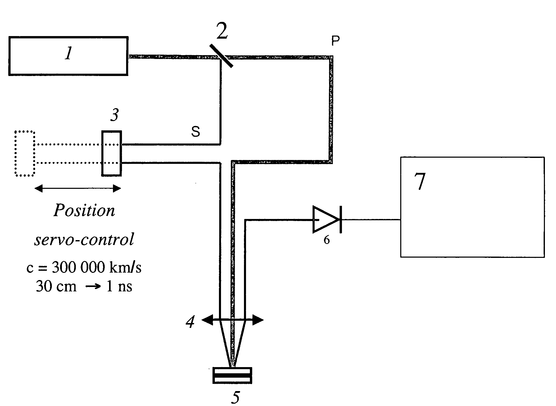
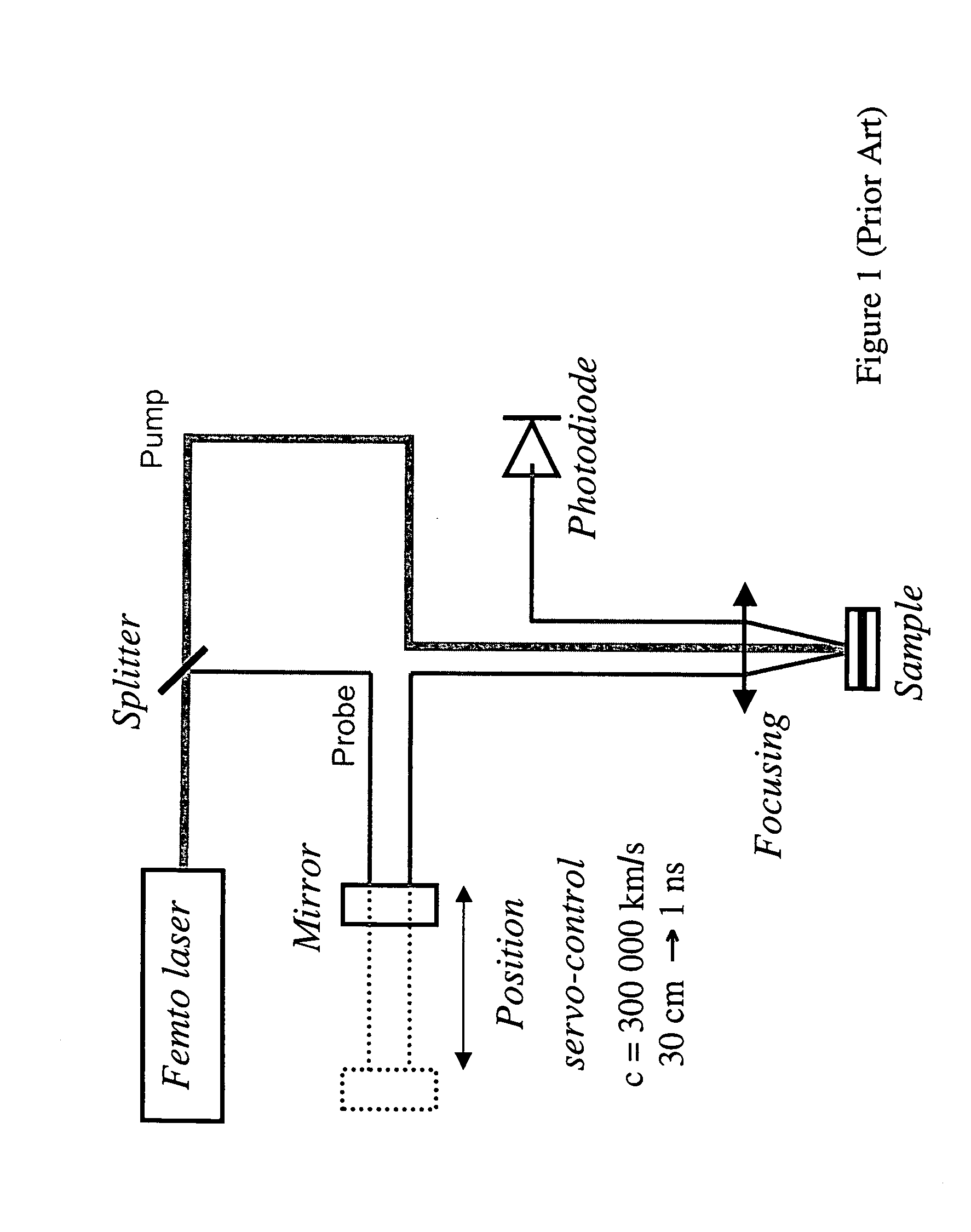
[0027]In a first embodiment, the source is wavelength-tunable via a tunable oscillator of the titanium-sapphire type that can generate pulses of 120 fs at a repetition rate of 76 MHz centered on a wavelength that is tunable in the range 700 nm to 990 nm. This source generates a signal that is split by a splitter 2 into a pump signal P and a probe signal S, both of which are designed to interact with the structure 5 to be analyzed. The probe signal S is subjected to a variation in optical path length relative to the pump signal P, e.g. via a moving mirror 3 that is position servo-controlled. Said probe signal is then focused on the structure 5 by an optical system 4, and is reflected towards detection means 6, e.g. of the photodetector type that are designed to generate a signal that can be analyzed by computation and processing means 7. Naturally, the probe signal can also be detected in transmission through the structure 5.

[0028]In order to enable the signals to go along the proper...

second embodiment

[0032]In a second embodiment, the source 1 makes it possible to generate a continuum of light extending over a wide wavelength range. In which case, the detector means 6 can comprise a spectrometer (not shown) serving to analyze the intensity of the light received before transmitting the signal to be analyzed to the processor means 7. Any system of filters in front of a usual photodetector can also be used. The plurality of wavelengths is then achieved continuously, e.g. by a fixed-wavelength femtosecond laser associated with an optical fiber.

[0033]In general, it is understood that the type of source used is not limiting to the present invention and that any type of source 1 making it possible to generate short laser pulses corresponding to a discrete or continuous set of wavelengths can be used. Similarly, in all of the embodiments, it is possible to use any means suitable for generating a time shift between the pump first beam and the probe second beam. This shift can thus be gene...


PUM


Abstract

The invention relates to a structure characterising device comprising means which are used for generating a first pump radiation and a second probe radiation and for transmitting different wavelength radiation, means for producing a time offset between said first pump and second probe radiation on the structure by means of detecting means of said second beam after the reflection or transmission thereof to said structure in such a way that an analysis signal is generated, means for processing said signal and identifying an area corresponding to the signal jump, for determining the jump amplitude according to different wavelengths, for comparing said amplitude with a theoretical amplitude variation pattern according to the wavelengths and for determining, for the wavelength characteristic for said theoretical pattern, a characteristic value associated to the structure thickness and to the radiation propagation velocity in said structure.

Description

CROSS REFERENCE TO RELATED APPLICATIONS[0001]This application is a National Stage of PCT / FR2006 / 001386, filed Jun. 19, 2006, which claims priority to French Application No. 0551673, filed Jun. 20, 2005, both of which are incorporated by reference herein.BACKGROUND AND SUMMARY[0002]The present invention relates to the field of methods of measuring the properties of structures. The present invention relates more particularly to a method of characterizing a structure by means of an acoustic wave generated and detected by light pulse. The method uses measurement of the various reflections and propagations of the wave in the structure.[0003]In the prior art, known U.S. Pat. No. 5,748,318 describes a system for the characterization of thin films and interfaces between thin films through measurements of their mechanical and thermal properties. In the system described, light is absorbed in a thin film or in a structure made up of several thin films, and the change in optical transmission or...

Claims


Application Information

Patent Timeline
IPC IPC(8): G01J1/00
CPCG01N2021/1706G01N21/1702
Inventor DEVOS, ARNAUDCARUYER, GREGORY
Owner CENT NAT DE LA RECHERCHE SCI
Why Eureka
Try Eureka