
Device for Casting

a casting device and technology for casting, applied in casting apparatus, metal-working equipment, manufacturing tools, etc., can solve the problems of high energy requirements for this process, low strength-to-weight ratio of plastic, and difficulty in recycling and separating plastic from other materials in automobiles, etc., to achieve economic and practical reproduction, simple design, and low cost

Inactive Publication Date: 2009-01-01
STONE ASHLEY
View PDF9 Cites 7 Cited by
  • Summary
  • Abstract
  • Description
  • Claims
  • Application Information

AI Technical Summary

Benefits of technology

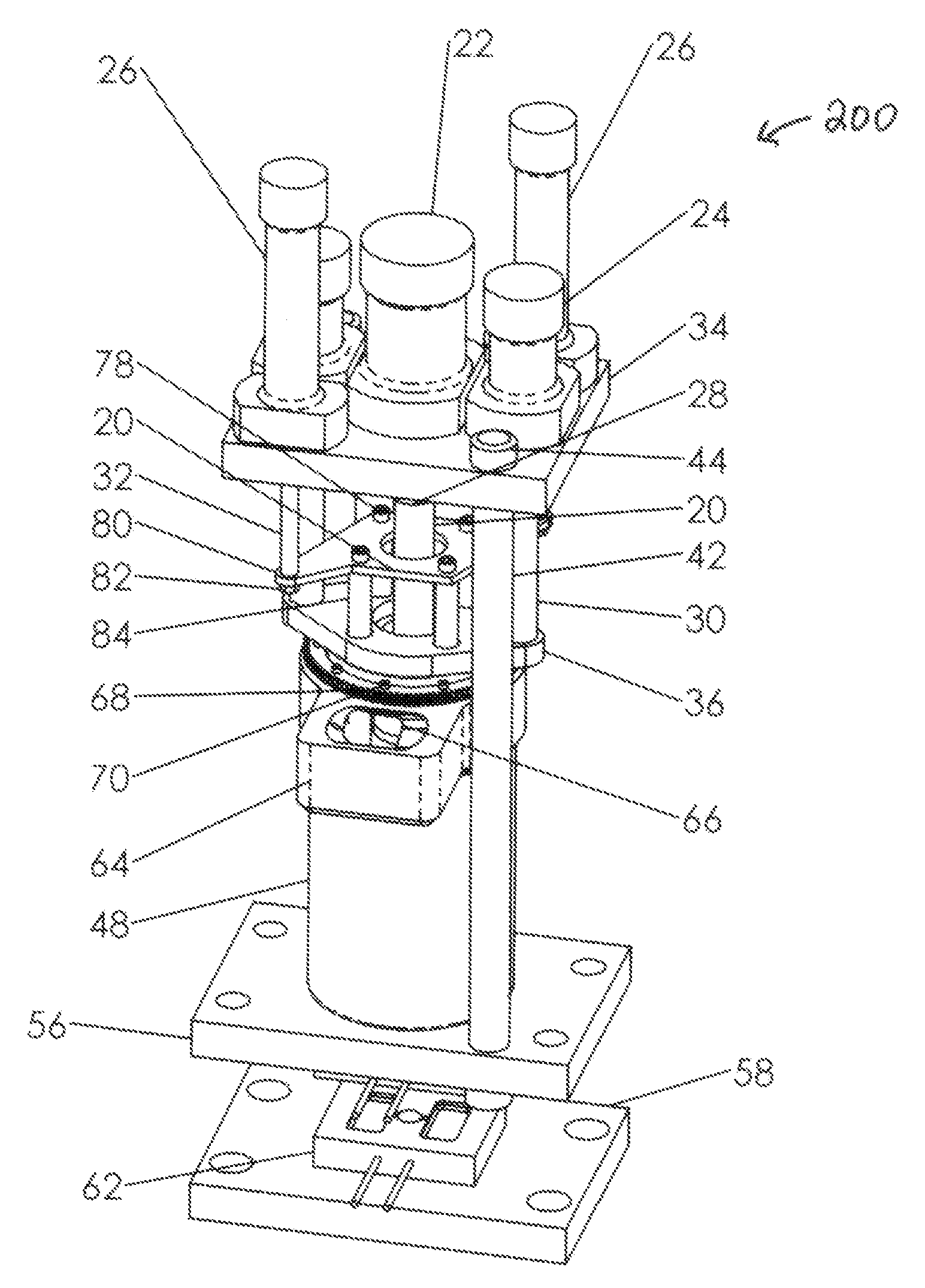
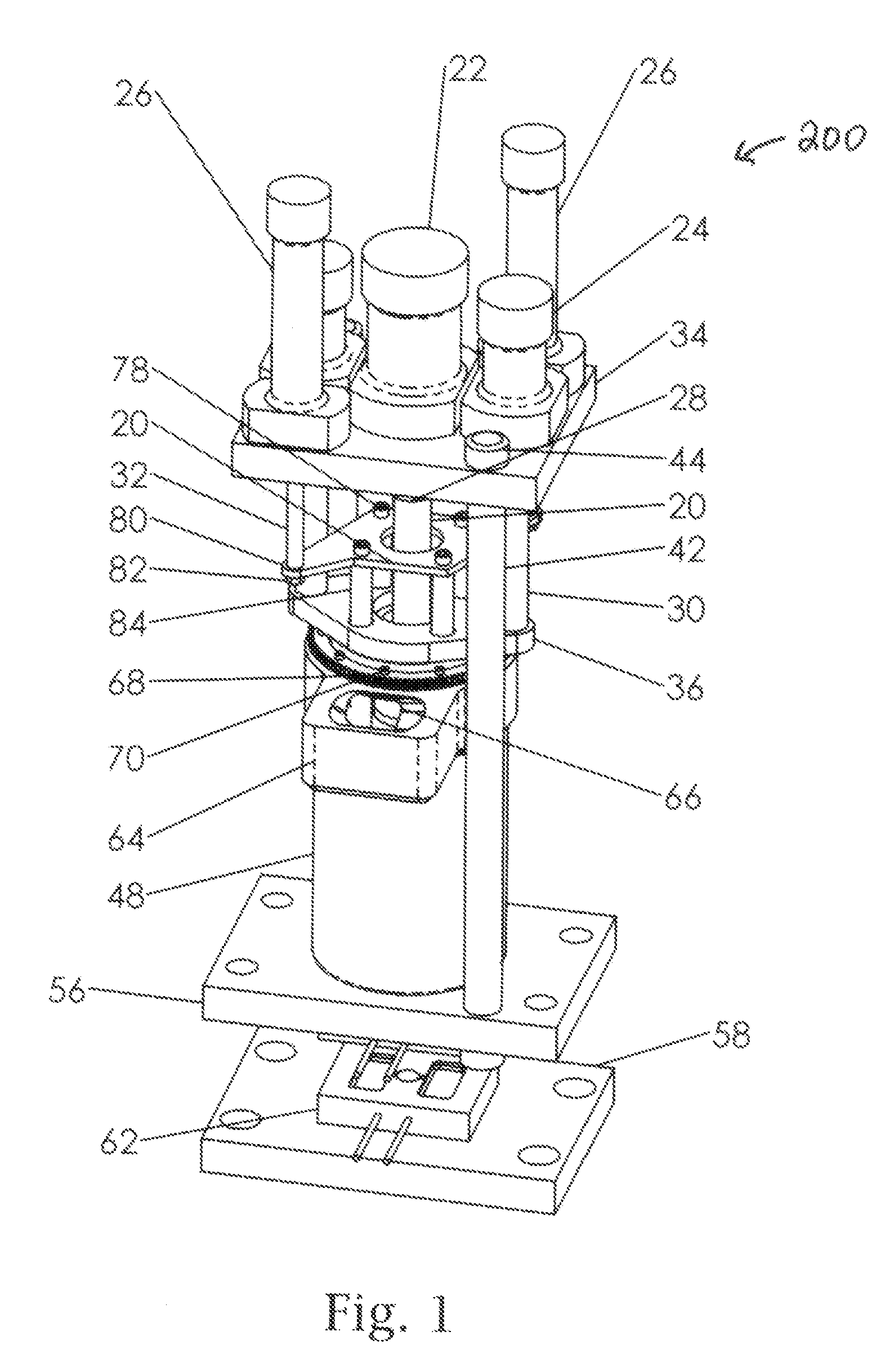
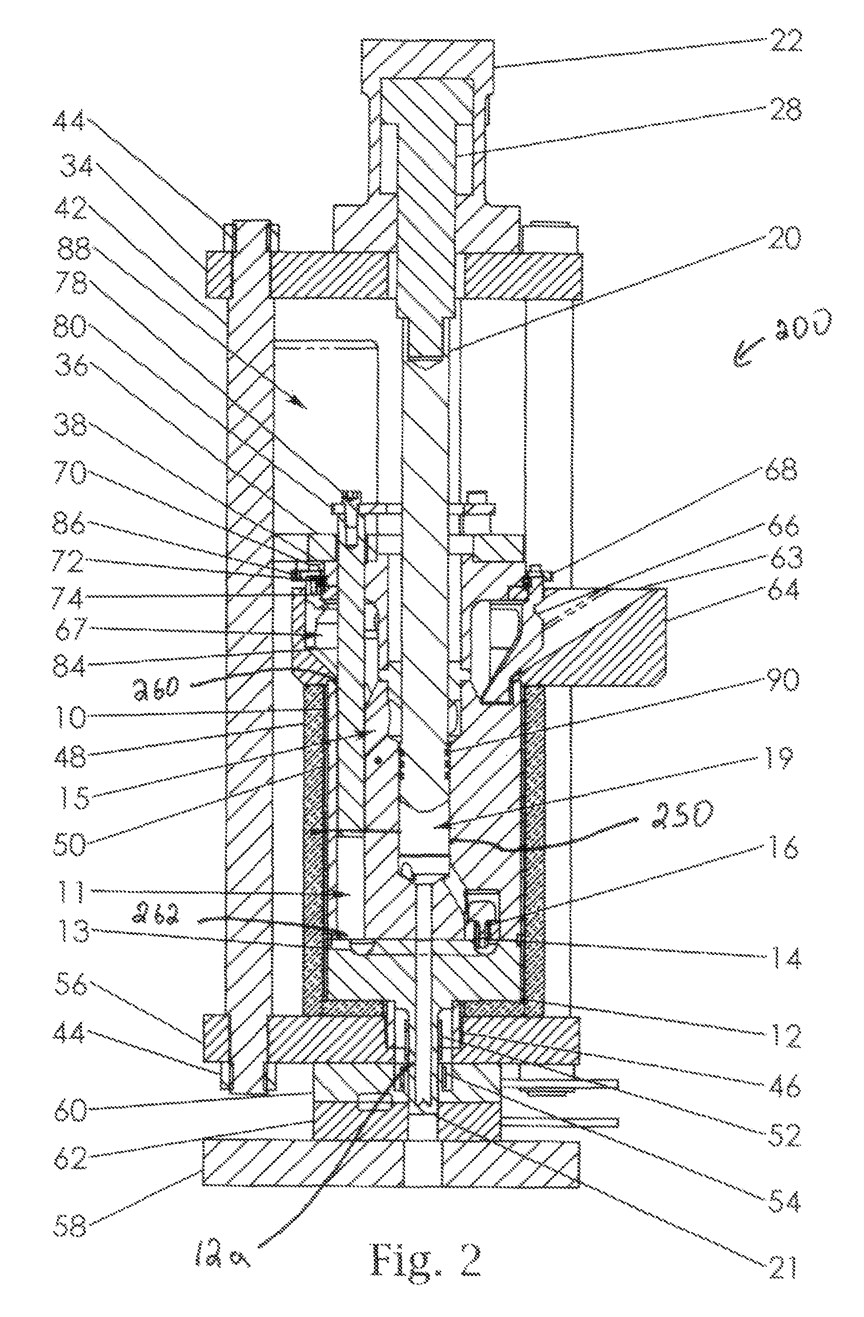
[0015]It is an object of the present invention to provide a casting machine having a simple design which is economic and practical to reproduce and yet overcomes the disadvantages of the prior art while enabling the casting of parts having very few defects. A casting machine made in accordance with one aspect of the present invention includes a processing cylinder formed in a thermally conductive block, said processing cylinder having a processing chamber and opposite first and second ends, the first end of the processing cylinder being configured to receive the metal feed stock. The machine further includes an injector cylinder formed in the thermally conductive block adjacent the processing cylinder, the injector cylinder having a shooting pot coupled to the second end of the processing cylinder by a passage configured to permit feed stock to pass from the processing cylinder into the shooting pot, a nozzle coupled to the injector cylinder configured to couple to the mold. The device includes a processing drive for driving the feed stock from the first end of the processing cylinder through the passage into the shooting pot and a heater thermally coupled to the processing cylinder. The heater and processing cylinder are configured to heat the feed stock such that the feed stock becomes progressively more liquid as it passes from the first to the second end of the processing cylinder. The machine further includes an injector plunger coupled to an injector actuator for driving the plunger sufficiently to force the metal from the shooting pot through the nozzle and into the mold.

Problems solved by technology

Today, automobile manufacturers are using more and more plastics, but plastic's strength to weight ratio is low when compared to light metals like aluminum, and in particular magnesium.
Plastic also has the disadvantage of being difficult to recycle and separate it from other materials in automobiles.
Intense energy requirements for this process are a major drawback for this technology.
Furthermore, handling the melt in the manufacturing process is riddled with losses and melt contamination.
Intense oxidation of the melt results in poor castings.
Injection of material into the cavity requires high speed, and turbulence from the process often results in extensive inclusions in the castings.
Defects of this nature are detrimental for applications in the automotive industry, particularly for castings related to vehicle safety.
It was said that this process can produce net-shape metal parts at a lower cost but this has not been the case under real market conditions.
These machines are very expensive and complex, difficult to operate and support.
However, high temperature and continued exposure to aggressive melt creates severe material deterioration problems.
As is well known, both processes suffer poor reliability due to lack of suitable materials for melt containment and no means to overcome melt corrosion and high pressure and high applicable temperature.
Both processes suffer from material shrinkage in the cast parts, from 5-15%.
High injection rates also cause gases to be mixed into the melt and becoming trapped in the part.
Molded metallic parts with high porosity are not desirable because of their reduced mechanical strength.
It is because of this that it is very difficult to accurately dimension conventionally die cast parts, and it is even more difficult to maintain the dimensions throughout life cycle of the part.
Therefore, the quality of the components made on these machines is generally poor and often does not meet the stricter requirements for the automobile industry.
Unfortunately, producing scrap still requires energy to remelt the part, and cover gases, such as sulfur hexafluoride (SF6) and carbon dioxide (CO2) are wasted.
Both gases have a significant environmental impact.
Besides environmental pollution, cast parts made from super heated melt are often plagued by entrapped porosities and inclusions created by large amounts of shrinkage due to rapid material cooling from superheated melt to solid near net shape parts.
However, one familiar with this state of the art will appreciate that the thixomolding® and similar semi-solid processes are complex and require a very long melt passageway.
Manufacturing suitable barrels is a tedious and requires expensive alloys and processes.
As a result only a few suppliers are able to produce composite barrels with Stellite liners in Inconel housings with the dimensional requirements for large throughput for any serious part molding using these methods.
It is very difficult to control all of the process parameters within a single cylindrical housing, particularly temperature, shot volume, pressure, cycle time, etc., and as a result, inconsistent characteristics of the molded metallic parts are produced.
As a consequence, if a molded metallic part of undesired characteristics is produced by a semi solid slurry molding machine, recycling of the defective part is not possible.
Metal parts molded by injection molding machines with high solid contents may have an uneven surface.
Such metal parts may require further processing before they can be painted.
Finally, the above mentioned injection molding process is complex and expensive to manufacture, and is plagued by the reliability of its machine parts.
Further, it lacks the wide operating window and stability that are required for a viable manufacturing process.
Both processing routes are largely unreliable and suffer from a lack of consistency from shot to shot and part to part.
Oil is environmentally unfriendly and there is a need to eliminate the oil for any kind of cooling on the machine.

Method used


Image

  • Device for Casting
  • Device for Casting
  • Device for Casting

Examples


Embodiment Construction

[0032]In the description of the preferred embodiment which follows, the cast part is preferably produced from magnesium alloy, preferably AZ91D, in a novel machine that will be illustrated and described below. This apparatus and method of casting high integrity parts is not limited to magnesium alloys and is equally applicable to any other type of metal, such as aluminum (Al), zinc alloys and any other alloy suitable for semisolid or liquidus processing. A high integrity part is understood to be one with minimal or no porosity or inclusions and metallurgical composition with a preferred dendrites free structure. Furthermore, specific temperature ranges used in the description will be relevant for magnesium alloy, but do not preclude the use of other alloys. The maximum operating temperature for this invention is preferably 700° C., however the actual operating temperature is limited only by the current availability of special materials capable of withstanding the harsh conditions im...


PUM

PropertyMeasurementUnit
melt temperatureaaaaaaaaaa
liquidus temperatureaaaaaaaaaa
shrinkageaaaaaaaaaa

Abstract

The present invention is a casting machine for casting parts in a mold out of a metal using a metal feed stock. The machine includes a processing cylinder formed in a thermally conductive block, said processing cylinder having a processing chamber and opposite first and second ends, the first end of the processing cylinder being configured to receive the metal feed stock. The machine further includes an injector cylinder formed in the thermally conductive block adjacent the processing cylinder, the injector cylinder having a shooting pot coupled to the second end of the processing cylinder by a passage configured to permit feed stock to pass from the processing cylinder into the shooting pot, a nozzle coupled to the injector cylinder configured to couple to the mold. The device includes a processing drive for driving the feed stock from the first end of the processing cylinder through the passage into the shooting pot and a heater thermally coupled to the processing cylinder. The heater and processing cylinder are configured to heat the feed stock such that the feed stock becomes progressively more liquid as it passes from the first to the second end of the processing cylinder. The machine further includes an injector plunger coupled to an injector actuator for driving the plunger sufficiently to force the metal from the shooting pot through the nozzle and into the mold.

Description

CROSS REFERENCE TO RELATED APPLICATION[0001]This application claims the benefit of provisional patent application Ser. No. 60 / 907,533 filed Apr. 6, 2007 and provisional patent application Ser. No. 60 / 935,561 filed Aug. 20, 2007, the entirety of which are incorporated herein by reference.FIELD OF THE INVENTION[0002]The invention relates generally to devices for casting or molding parts.BACKGROUND OF THE INVENTION[0003]It is a trend to increase the strength and reduce the weight of all kinds of transportation vehicles (bikes, motorbikes, cars, trucks, aircraft, space shuttle and others). With reduced weight, reduced fuel consumption and reduced gas emissions to follow. Today, automobile manufacturers are using more and more plastics, but plastic's strength to weight ratio is low when compared to light metals like aluminum, and in particular magnesium. Plastic also has the disadvantage of being difficult to recycle and separate it from other materials in automobiles. Light alloy parts ...

Claims


Application Information

Patent Timeline
Patent Type & Authority Applications(United States)
IPC IPC(8): B22D17/04
CPCB22D17/007B22D17/20B22D17/2038B22D17/04B22D17/203B22D45/00
Inventor STONE, ASHLEYKESTLE, MARTIN R.
Owner STONE ASHLEY
Learn More