Bipolar transistor drivers

a transistor and driver technology, applied in the direction of pulse technique, process and machine control, instruments, etc., can solve the problems of affecting the aforementioned collector resistance, the breakdown voltage of the base-emitter junction, and the limitation of the amount of reverse base current that can be drawn, so as to facilitate the application of sufficient drive and facilitate the effect of rapid turning o

Inactive Publication Date: 2009-02-12
POWER INTEGRATIONS INC
View PDF27 Cites 69 Cited by
  • Summary
  • Abstract
  • Description
  • Claims
  • Application Information

AI Technical Summary

Benefits of technology

[0022]A similar effect may also be achieved using a transistor with an emitter or source connection coupled to the second plate of the capacitor preferably, to reduce the effects of stray capacitance, a second capacitor is coupled to the second side (plate) of the capacitor to provide a capacitative divider for voltage sharing between the two capacitors. In a resonant converter use of such a capacitor also has the advantage of providing an additional current path (for example to ground). A further advantage is that if the closed loop control system is implemented on an integrated circuit then a connection to the second side of the capacitor may be brought out on a pin (COL) and connecting a second capacitor to this pin effectively allows the sensed voltage to be scaled, facilitating operation of the system at a range of different collector voltages (since the internal collector resistance can vary with the high voltage device employed).
[0051]Adjusting the control drive to the transistor enables the transistor to be turned off faster; in embodiments the charge storage time may be controlled to substantially achieve a set or desired duration.

Problems solved by technology

There are various limitations on the amount of reverse base current that can be drawn, such as lateral base resistance, base-emitter junction breakdown voltage, and charge drift velocity from the collector into the base.
One technique for regulating the base current for switching a bipolar transistor is described in U.S. Pat. No. 5,017,802 but this circuit has the drawback that it is affected by the aforementioned (variable) collector resistance.
However when a transistor is in quasi-saturation as described above the collector voltage can be greater than the base voltage and this type of clamp can fail.

Method used


Image

  • Bipolar transistor drivers
  • Bipolar transistor drivers
  • Bipolar transistor drivers

Examples


Embodiment Construction

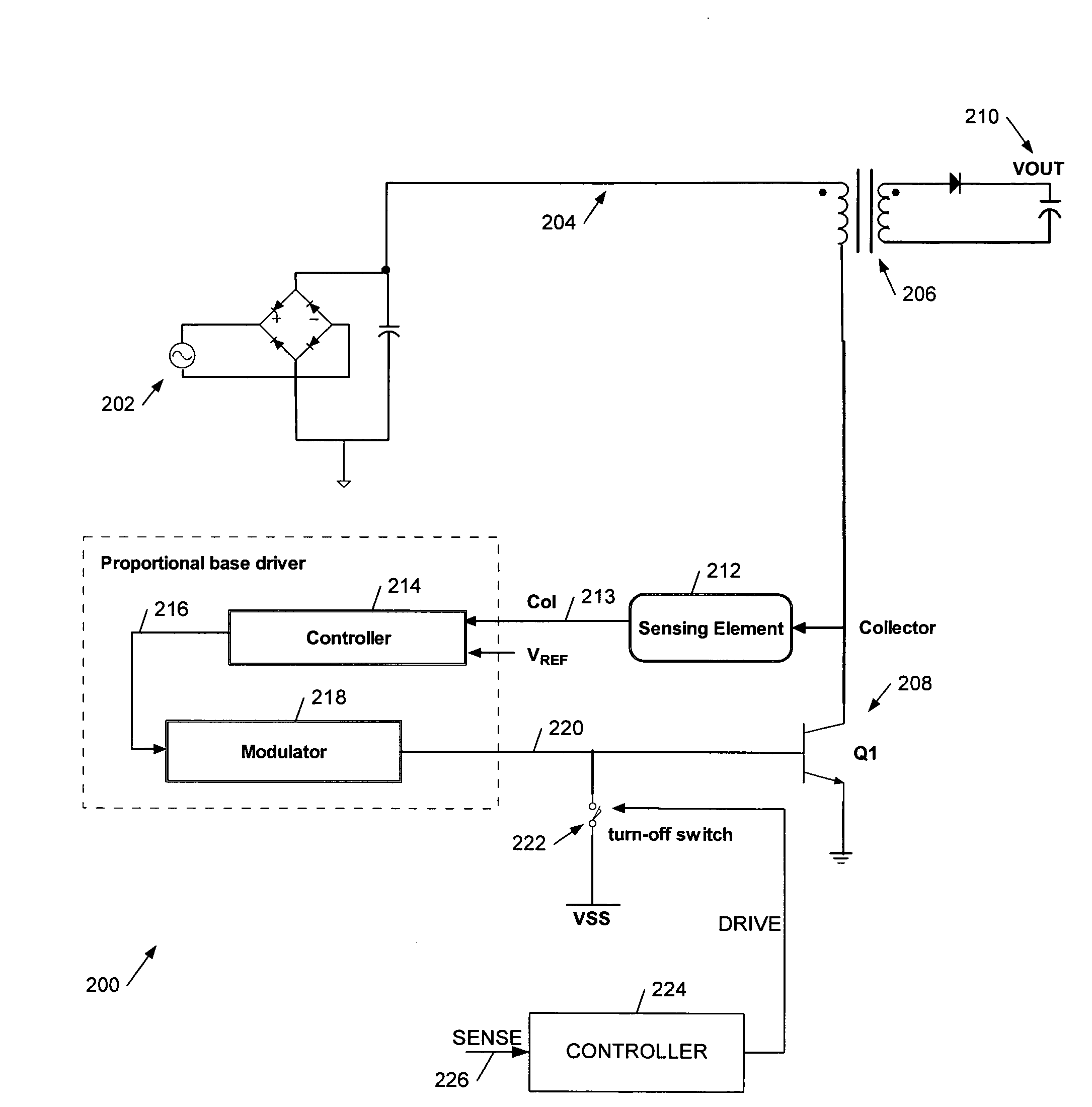
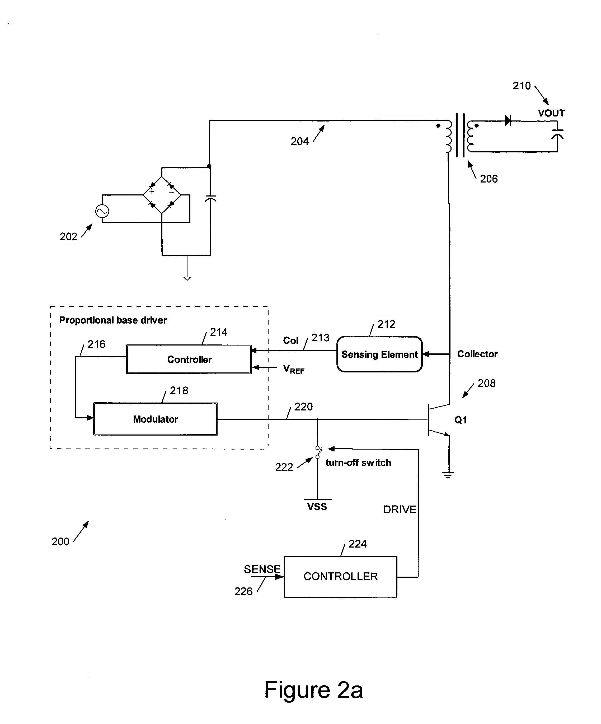
[0100]Broadly speaking we will describe an apparatus and related method for controlling the level of base current to minimise the total losses in the primary switching transistor. In embodiments we control the base drive current to avoid excess stored charge at a desired instant of turn-off, in order to minimise turn-off time. This is done by measuring the collector voltage. Although preferred applications of the techniques we describe are in the field of power converters, the techniques may be used more generally where bipolar transistors are employed for cyclic switching, in particular where it is desired to achieve both a low on-state voltage (collector to emitter) and a fast turn-off. However such a combination is particularly desirable in power converters, to minimise power losses and to optimise control, for example to limit output current in overload conditions. Use of a bipolar switching resistor in a power converter can provide a significant cost saving as compared with, sa...


PUM


Abstract

We describe a switching power converter comprising a bipolar switching device (BJT or IGBT) switching an inductive load, and including a closed-loop control system. The control system comprises a voltage sensing system to sense a voltage on a collector terminal of the switching device and provide a voltage sense signal; a controller; and a drive modulation system coupled to an output of the controller for modulating a drive to the control terminal of said bipolar switching device responsive to a controller control signal; wherein said controller is configured to monitor changes in the sensed voltage during a period when said switching device is switched on and to control said drive modulation system to control the degree of saturation of said bipolar switching device when the device is switched on and hence improve turn-off times.

Description

RELATED APPLICATION[0001]This application claims priority under 35 U.S.C. 119 to United Kingdom Application No. 0708196.1, filed Apr. 27, 2007, which application is incorporated herein by reference and made a part hereof.FIELD OF THE INVENTION[0002]This invention relates to methods and apparatus, both analogue and digital, for driving bipolar switching devices such as a bipolar junction transistor (BJT) or insulated gate bipolar transistor (IGBT), in particular to control the degree of saturation when the device is on and hence improve turn-off times.BACKGROUND TO THE INVENTION[0003]FIG. 1a shows a typical high voltage NPN transistor which has a heavily N+ doped emitter, a moderately P doped base region and a lightly N doped collector, with a Heavily N+ doped collector ohmic contact.[0004]With a high voltage on the collector, the collector-base junction is reverse-biased, and a charge depletion region extends largely into the collector due to its lower doping level. If a forward cur...

Claims


Application Information

Patent Timeline
Patent Type & Authority Applications(United States)
IPC IPC(8): H02M3/335H03K17/0422H02H7/122
CPCH02M3/33507Y02B70/1433H03F3/45183H03F2203/45322H03F2203/45352H03F2203/45396H03F2203/45466H03F2203/45506H03K17/0406H03K17/0422H03K17/0826H03K17/0828H03K17/567H03K17/64H03F3/2171Y02B70/10H03K17/16H03K17/168H02M1/32H02M3/33538
Inventor LALITHAMBIKA, VINOD A.RYAN, PAULGARNER, DAVID M.JACQUES, RUSSELL
Owner POWER INTEGRATIONS INC
Why Eureka
Try Eureka