Quantum cryptography transmission system and optical device

a transmission system and quantum cryptography technology, applied in the field of quantum cryptography transmission system, can solve the problems of unbalanced optical delay of mach-zehnder, unbalanced polarization coding, and the threat to the progress of computer hardware and decryption algorithms, so as to achieve the effect of reducing the economic and technologic burden of the device of a regular user, simplifying the configuration of the device, and facilitating the operation of the devi

Inactive Publication Date: 2009-02-19
NEC CORP
View PDF6 Cites 14 Cited by
  • Summary
  • Abstract
  • Description
  • Claims
  • Application Information

AI Technical Summary

Benefits of technology

[0061]The present invention has been made in light of the problems held by the above-mentioned related art, and the object thereof is to provide a quantum cryptography transmission system wherein a device to be possessed by a regular user can have a more simple configuration than that of the related art, and also includes no risk of a Trojan horse type attack by an eavesdropper, and an optical circuit employed therewith. An optical circuit according to the present invention is characterized so as to include an unbalanced Mach-Zehnder interferometer including an optical delay circuit in one arm thereof, and means for applying propagation delay equivalent to the propagation length of the optical delay circuit between photons for propagating a different port.
[0063]According to the present invention, the configuration of a device to be possessed by a regular user can be simplified, and handling thereof can be readily performed. Accordingly, economic and technologic burden for the device of a regular user and operation of the device can be extremely reduced as compared to the quantum cryptography devices disclosed in Non-patent Documents 1 through 8 and Patent Document 1. Simultaneously, a quantum cryptography device having safety as to a Trojan horse type attack can be provided.

Problems solved by technology

However, these are based on computational complexity safety.
That is to say, the present encryption scheme is threatened with progress of computer hardware and decryption algorithms.
Note however, polarization coding needs real-time control and compensation of polarization rotation within a transmission path, so is not frequently employed as a method for implementing a long-distanced cryptographic key distribution system employing an optical fiber as a transmission path.
Note however, this device includes a problem wherein the relative optical delay of the unbalanced Mach-Zehnder interferometers 72 and 74 which the transmission unit 10B and the reception unit 20B have, respectively, needs to be maintained with precision equivalent to a light wavelength.
Such a measuring device itself complicates the system, and also reference light employed for measurement increases system noise, and becomes a cause of deterioration in performance of the quantum cryptography device.
With the planar lightwave circuit technology, an unbalanced Mach-Zehnder interferometer is fabricated on a silicone substrate using an optical waveguide formed with patterning.
In the case of implementation employing the PLC, with the current technology, a low-loss unbalanced Mach-Zehnder interferometer including a phase modulator described above cannot be readily fabricated.
Even though increase in cost is no problem, increase in optical loss of the reception-side device is directly connected to deterioration in performance of a quantum cryptography device employing attenuated light as information carriers, so this is an unacceptable problem.
The quantum cryptography device employing the above-mentioned PLC is confirmed to have functioned, but active modulation by a phase modulator is needed to execute a quantum cryptographic key distribution protocol, and bias control for safe control of the phase modulator is also needed, and consequently, the device has become complicated.
Also, a so-called Trojan horse type attack, wherein an eavesdropper wire-taps the value of phase modulation of a modulator by introducing a probe light externally, is theoretically possible, which poses a problem in that safety guarantee as to such a type of attack cannot be obtained.
In brief, the quantum cryptography devices by phase coding which is the related art shown in Non-patent Documents 1 through 4 need to maintain the relative difference of the optical path length of the two unbalanced Mach-Zehnder interferometers for long time, and accordingly, an active control device is needed, which complicates the devices.
This problem can be avoided by the two unbalanced Mach-Zehnder interferometers being configured of the PLC, such as shown in Non-patent Documents 5 through 7 and Patent Document 1, but this requires an active signal modulation device and the control system thereof, and accordingly, the device is complicated.
That is to say, regardless of which implementation method including the quantum cryptography device disclosed in Non-patent Document 8 is selected, complication of the device cannot be readily avoided.
Also, with each method, active signal modulation is performed, leaving the risk of a Trojan horse type attack by an eavesdropper.

Method used


Image

  • Quantum cryptography transmission system and optical device
  • Quantum cryptography transmission system and optical device
  • Quantum cryptography transmission system and optical device

Examples


first embodiment

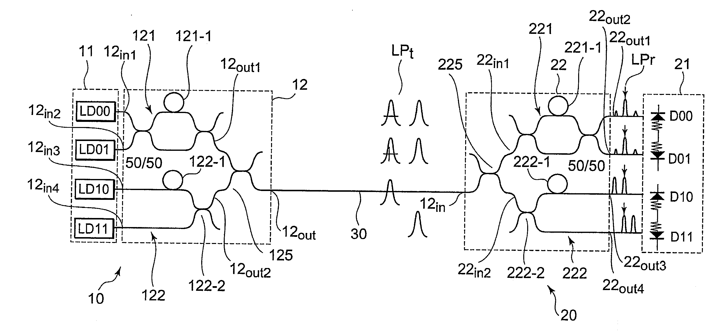
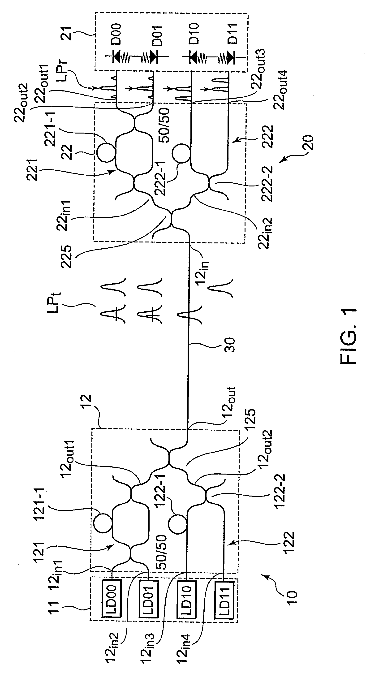
[0076]FIG. 1 is a configuration diagram illustrating a quantum cryptography transmission system according to the present invention. The illustrated quantum cryptography transmission system is configured of a quantum cryptography transmission device 10, a quantum cryptography reception device 20, and an optical fiber transmission path 30 connecting between these.

[0077]The quantum cryptography transmission device 10 is configured of a light emitting unit 11 consisting of first through fourth weak laser light sources LD00, LD01, LD10, and LD11, and a transmission-side optical circuit 12. The first through fourth light sources LD00 through LD11 generate first through fourth photons serving as quantum bit information carriers, respectively. In the example being illustrated, the light emitting unit 11 is configured of the first through fourth light sources LD00 through LD11, but it goes without saying that the present invention is not restricted to this. Regardless, all that is required f...

second embodiment

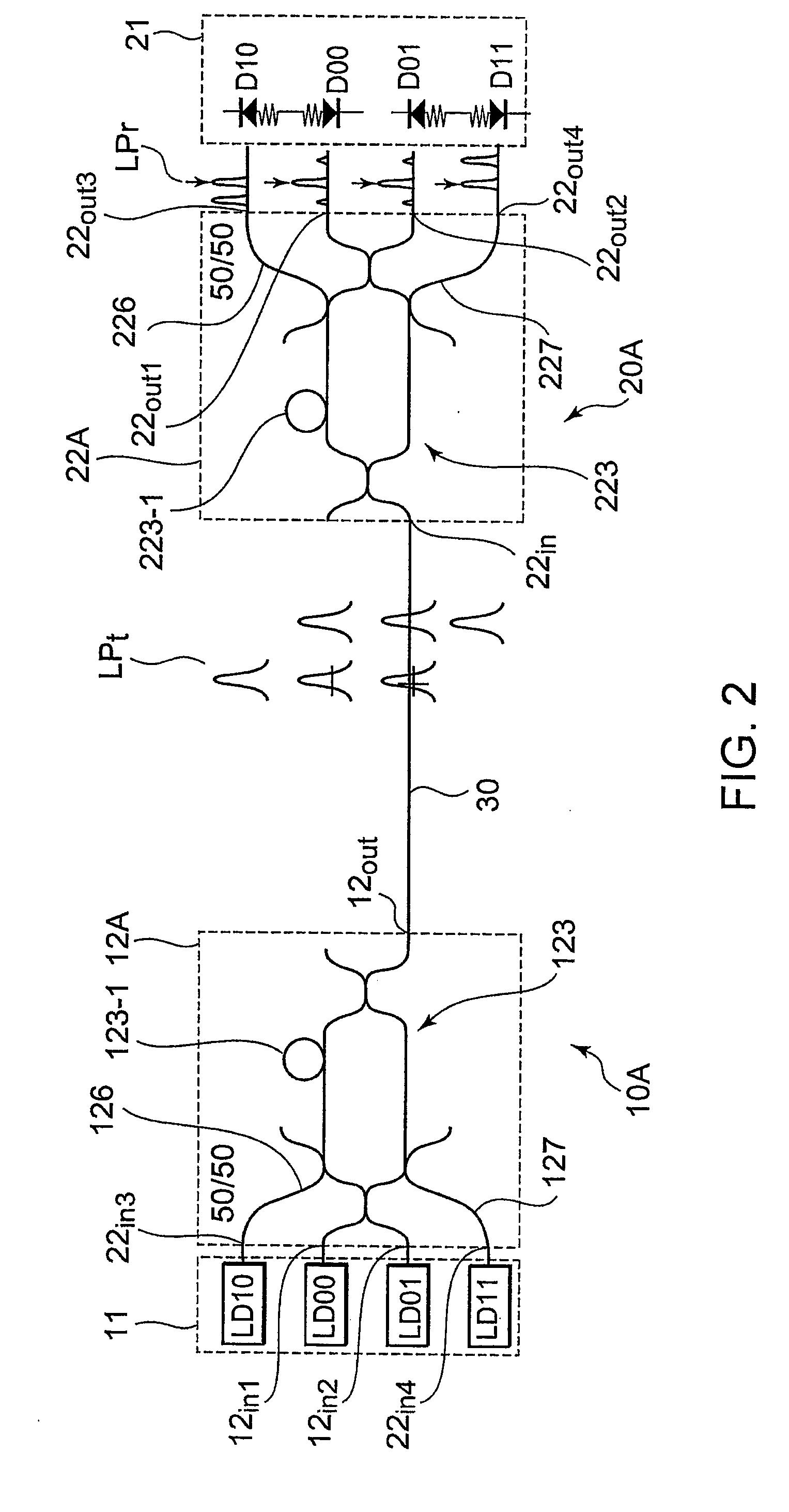
[0084]FIG. 2 is a configuration diagram illustrating a quantum cryptography transmission system according to the present invention. The illustrated quantum cryptography transmission system is configured of a quantum cryptography transmission device 10A, a quantum cryptography reception device 20A, and an optical fiber transmission path 30 connecting between these.

[0085]The quantum cryptography transmission device 10A has the similar configuration as that of the quantum cryptography transmission device 10 shown in FIG. 1 except that the configuration of the transmission-side optical circuit differs from that shown in FIG. 1. Accordingly, the transmission-side optical circuit is denoted with reference numeral 12A.

[0086]The transmission-side optical circuit 12A is configured of a transmission-side unbalanced Mach-Zehnder interferometer 123 and two transmission-side 3-dB couplers 126 and 127 to be connected to the two arms of the transmission-side unbalanced Mach-Zehnder interferometer ...

third embodiment

[0116]FIG. 3 is a configuration diagram illustrating a quantum cryptography transmission system according to the present invention. The illustrated quantum cryptography transmission system is configured of a photon pair generating source 40 disposed in the center, and a pair of quantum cryptography reception devices 20 disposed on both sides thereof. The photon pair generating source 40 and each of the quantum cryptography reception devices 20 are connected with the optical fiber transmission path 30 for transmitting attenuated light.

[0117]Each of the quantum cryptography reception devices 20 has the similar configuration as that of the quantum cryptography reception device 20 illustrated in FIG. 1. That is to say, the quantum cryptography reception device 20 on the right side is configured of the reception-side optical circuit 22, and a light receiving unit 21 including first through fourth photon detectors A00, A01, A10, and A11. The quantum cryptography reception device 20 on the...


PUM


Abstract

A quantum cryptography transmission system according to the present invention comprises a transmission device (10A), a reception device (20A), and a transmission path (30) configured to connect between the devices. The transmission device includes a light emitting unit (11) configured to emit photons serving as quantum bit information carriers, and a transmission-side optical circuit (12A). The reception device includes a light receiving unit (21) configured to detect photons serving as quantum bit information carriers, and a reception-side optical circuit (22A). Each of the transmission-side optical circuit (12A) and reception-side optical circuit (22A) is an optical circuit which is configured of an unbalanced Mach-Zehnder interferometer (123; 223) including an optical delay circuit (123-1; 223-1) in one arm thereof, and two transmission-side 3-dB couplers (126; 226) and (127; 227) to be connected to the two arms of the unbalanced Mach-Zehnder interferometer (123; 223), respectively.

Description

TECHNICAL FIELD[0001]The present invention relates to a quantum cryptography transmission system, and particularly relates to a quantum cryptography transmission system for performing a quantum cryptographic key distribution wherein cryptographic secret key is shared by optical fiber communication, and an optical circuit employed therewith.BACKGROUND ART[0002]In recent years, explosive growth of the Internet and practical realization of e-commerce have enhanced social need for cryptography technology, such as communicative maintenance of secret, prevention from tampering, individual authentication, and so forth.[0003]Currently, a common key system such as DES (Data Encryption Standard) encryption and a public key system such as RSA (R. Rivest, A. Shamir, L. Adlman) encryption have come into widespread use. However, these are based on computational complexity safety.[0004]That is to say, the present encryption scheme is threatened with progress of computer hardware and decryption alg...

Claims


Application Information

Patent Timeline
Patent Type & Authority Applications(United States)
IPC IPC(8): H04L9/06H04K1/00
CPCH04L9/0852H04B10/70
Inventor NAMBU, YOSHIHIROYOSHINO, KENICHIROH
Owner NEC CORP
Why Eureka
Try Eureka