Optical fiber probe for side imaging and method of manufacturing the same

Inactive Publication Date: 2009-02-26
GWANGJU INST OF SCI & TECH
View PDF5 Cites 33 Cited by
  • Summary
  • Abstract
  • Description
  • Claims
  • Application Information

AI Technical Summary

Benefits of technology

[0022]Furthermore, during a process of manufacturing a lens-typed optical fiber, an optical fiber does not

Problems solved by technology

However, since a small-sized optical fiber needs to be coupled to a bulk element, such as a microprism or a reflection mirror, having a relatively large volume, a manufacturing process is complicated, and the size of the manufactured optic

Method used


Image

  • Optical fiber probe for side imaging and method of manufacturing the same
  • Optical fiber probe for side imaging and method of manufacturing the same
  • Optical fiber probe for side imaging and method of manufacturing the same

Examples


Embodiment Construction

[0036]The invention may be embodied in many different forms and have various embodiments. The invention will now be described more fully with reference to the accompanying drawings, in which preferred embodiments of the invention are shown. However, the invention should not be construed as being limited to the embodiments set forth herein, and it should be understood that all changes, modifications, and equivalents that fall within a technical sprit and scope of the invention are therefore intended to be embraced by the invention. Like reference numerals refer to like elements throughout the specification.

[0037]It will be understood that, although the terms first, second, etc. may be used herein to describe various components, the components should not be limited by these terms. These terms are only used to distinguish one component from another component. For example, a first component could be termed a second component, and the second component could be named the first component w...


PUM


Abstract

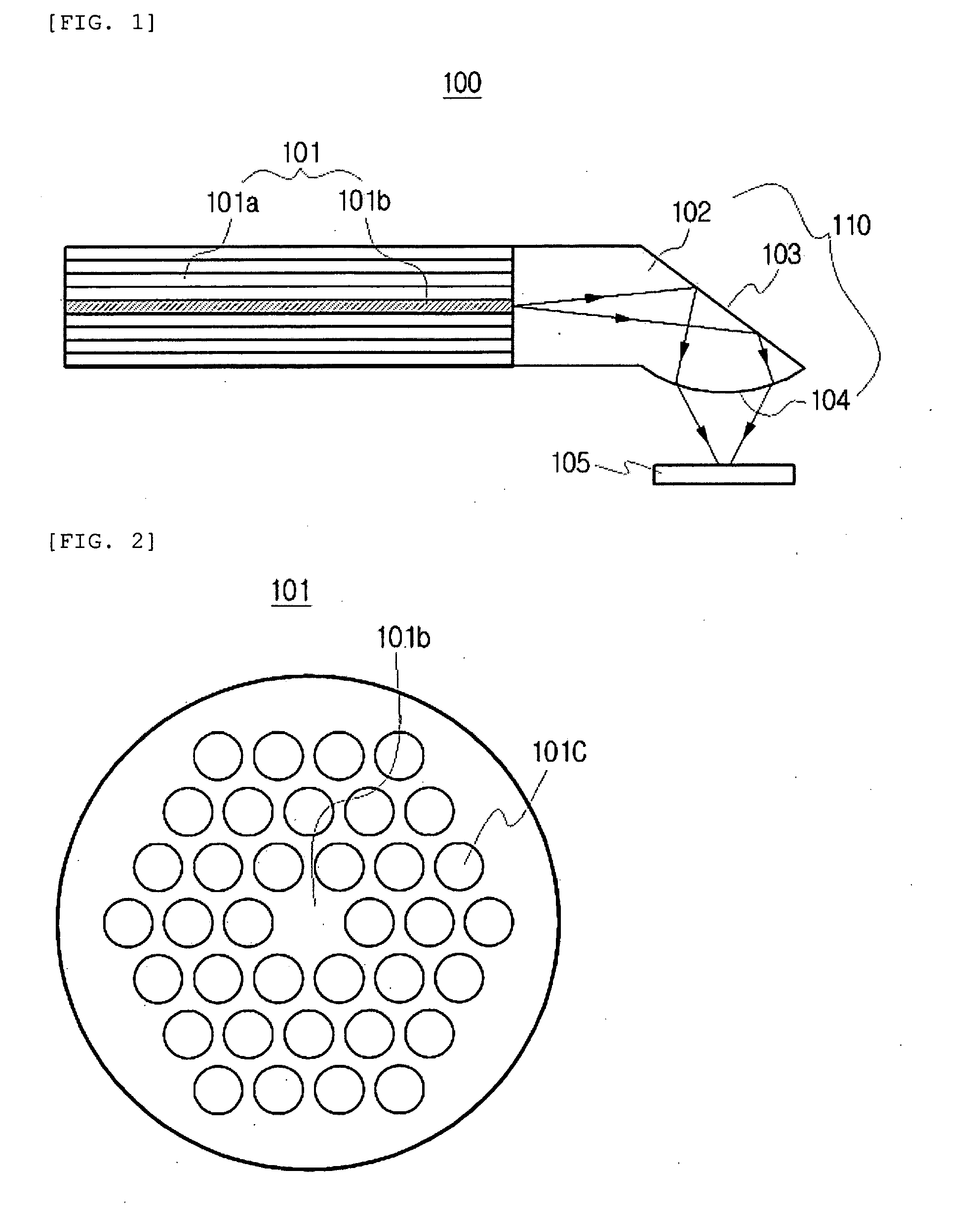
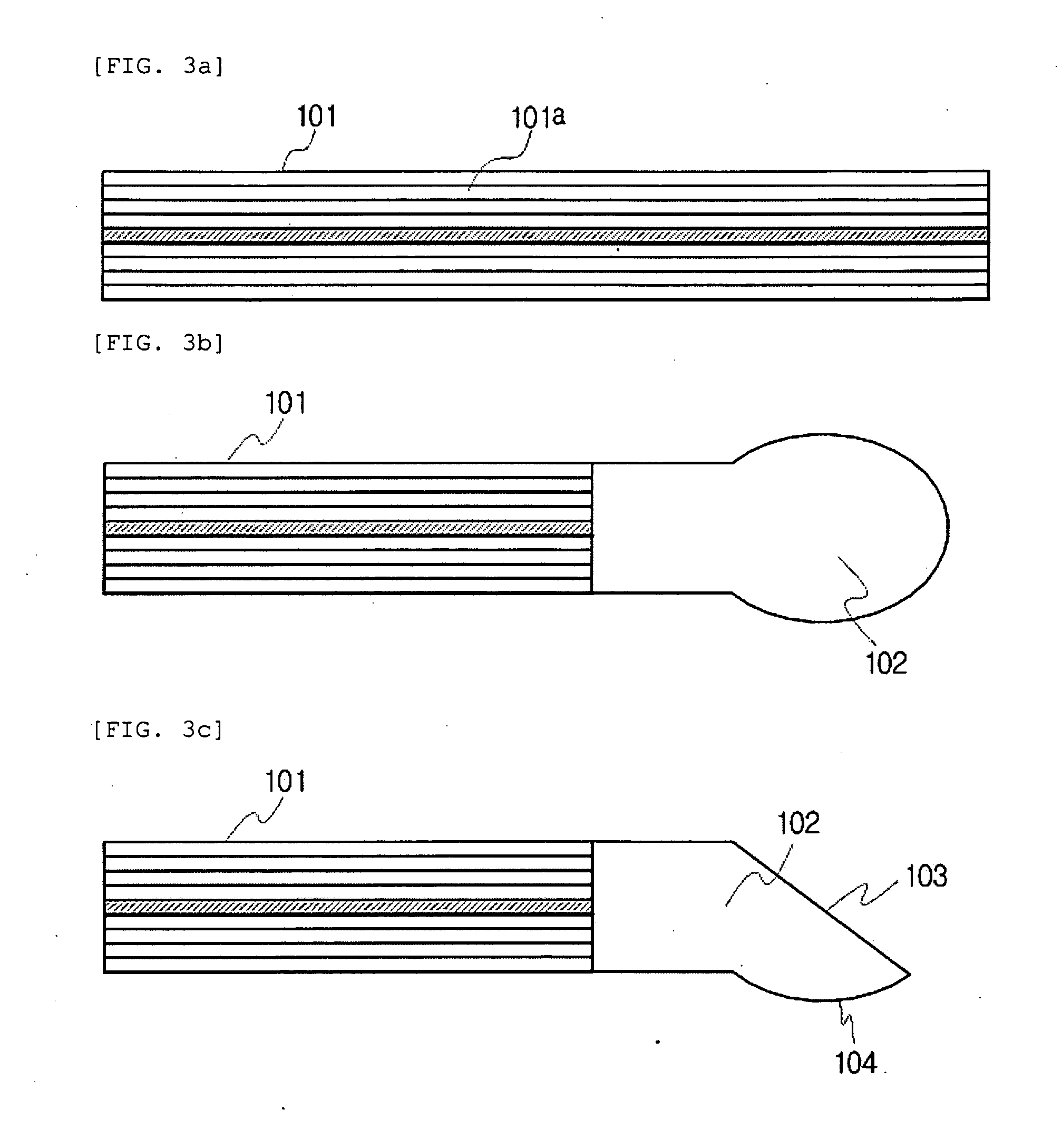
Disclosed are an optical fiber probe for side imaging and a method of manufacturing the same. An optical fiber probe according to an aspect of the invention includes a photonic crystal fiber, and an optical fiber lens that is formed by applying heat to a predetermined region including one end of the photonic crystal fiber and substantially removing air holes formed in the predetermined region. The optical fiber lens includes a light diffusion region that diffuses light propagating along a core of the photonic crystal fiber and focuses the light to enable side imaging, a reflector surface that reflects the light at a right angle to enable side imaging, and a lens surface that focuses the light. A small-sized optical fiber probe can be manufactured using a simple manufacturing process, and the optical fiber probe can be miniaturized. Therefore, a light measurement system can be miniaturized, which makes it possible to obtain side images of a very small sample, such as a blood vessel.

Description

BACKGROUND OF THE INVENTION[0001]1. Technical Field[0002]The present invention relates to an optical fiber probe and a method of manufacturing the same, and more particularly, to an optical fiber probe for side imaging and a method of manufacturing the same.[0003]2. Related Art[0004]An optical fiber lens has been used in a field of optical communication to improve optical coupling efficiency at the time of optical coupling between a light source or an optical element and an optical fiber or optical coupling between two optical fibers with a predetermined distance, and manufacture a small-sized module.[0005]In recent years, the optical fiber lens has been widely used for an imaging system using light or a medical treatment apparatus using a laser as well as the field of optical communication.[0006]In particular, an optical fiber probe has been used to miniaturize an imaging system using light.[0007]An optical fiber probe-based tomographic imaging system using light requires a light s...

Claims


Application Information

Patent Timeline
IPC IPC(8): G02B6/06
CPCA61B5/0066A61B5/0084G02B6/262G02B6/02347A61B5/02007G02B6/42
Inventor LEE, BYEONG HACHOI, HAE YOUNGRYU, SEON YOUNGNA, JIHOONSOHN, IK-BUNOH, YOUNG-CHULLEE, JONGMIN
Owner GWANGJU INST OF SCI & TECH
Why Eureka
Try Eureka