Ceramics heat exchanger

Active Publication Date: 2009-03-05
JAPAN ATOMIC ENERGY AGENCY INDEPENDANT ADMINISTRATIVE CORP
View PDF14 Cites 22 Cited by
  • Summary
  • Abstract
  • Description
  • Claims
  • Application Information

AI Technical Summary

Benefits of technology

[0030]The above-described ceramic heat exchanger of the present invention includes a heat exchange section that heat-exchanges between fluids A and B flowing in the direction in which the fluids oppose each other. The heat exchange section includes a plurality of ceramic blocks stacked one on top of another with a seal therebetween. Both ends in the stacking direction of the stack are bound to join and integrate the ceramic blocks with tightening means including end plates and a tie rod. The end plates are provided with a thermal expansion absorber on their external surface for absorbing the thermal expansion in the axial direction of the tie rod. Thus, the stack of

Problems solved by technology

In addition, the heat exchange section is used at high temperatures in the range of 400 to 800° C., and therefore, cannot use combinations of a polytetrafluoroethylene-based material and a metal generally used in sulfuric acid plants.
In the heat exchanger for thermochemical IS process hydrogen production apparatus running at a temperature of 400° C. or more, however, polytetrafluoroethylene or the like cannot be used, and heat exchangers made of ceramic, such as silicon carbide or silicon nitride, has been proposed from the viewpoint of corrosion resistance to sulfuric acid and heat resistance.
Unfortunately, ceramic is an elastic material, and has some disadvantages in use as a structural material in comparison with metals.
More specifically, first, ceramic is brittle and, accordingly, has low toughness.
Consequently, a crevice extends from a point undergoing stress concentration or a tiny crack, and may result in destruction.
Second, ceramic is difficult to join.
In order to achieve reliable joining, a furnace is required, and the size of the materials to be joined to each other is limited by the capacity of the furnace.
In addition, if a defect or uneven strength occurs at the joined

Method used


Image

  • Ceramics heat exchanger
  • Ceramics heat exchanger
  • Ceramics heat exchanger

Examples


first embodiment

FIGS. 1 to 8

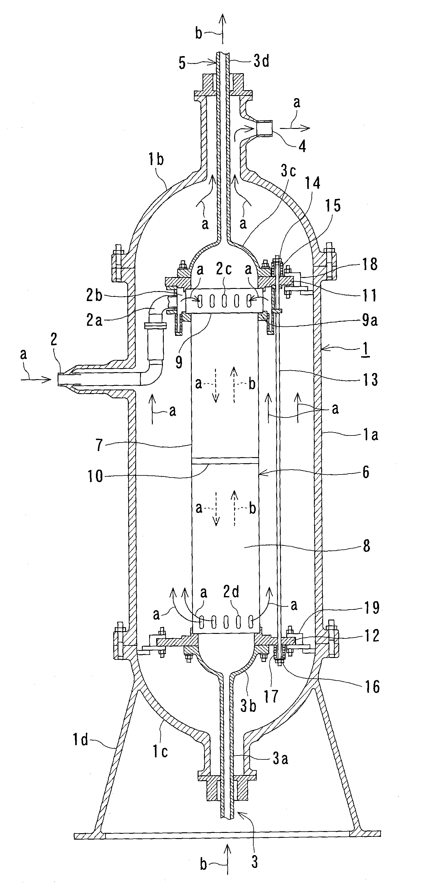
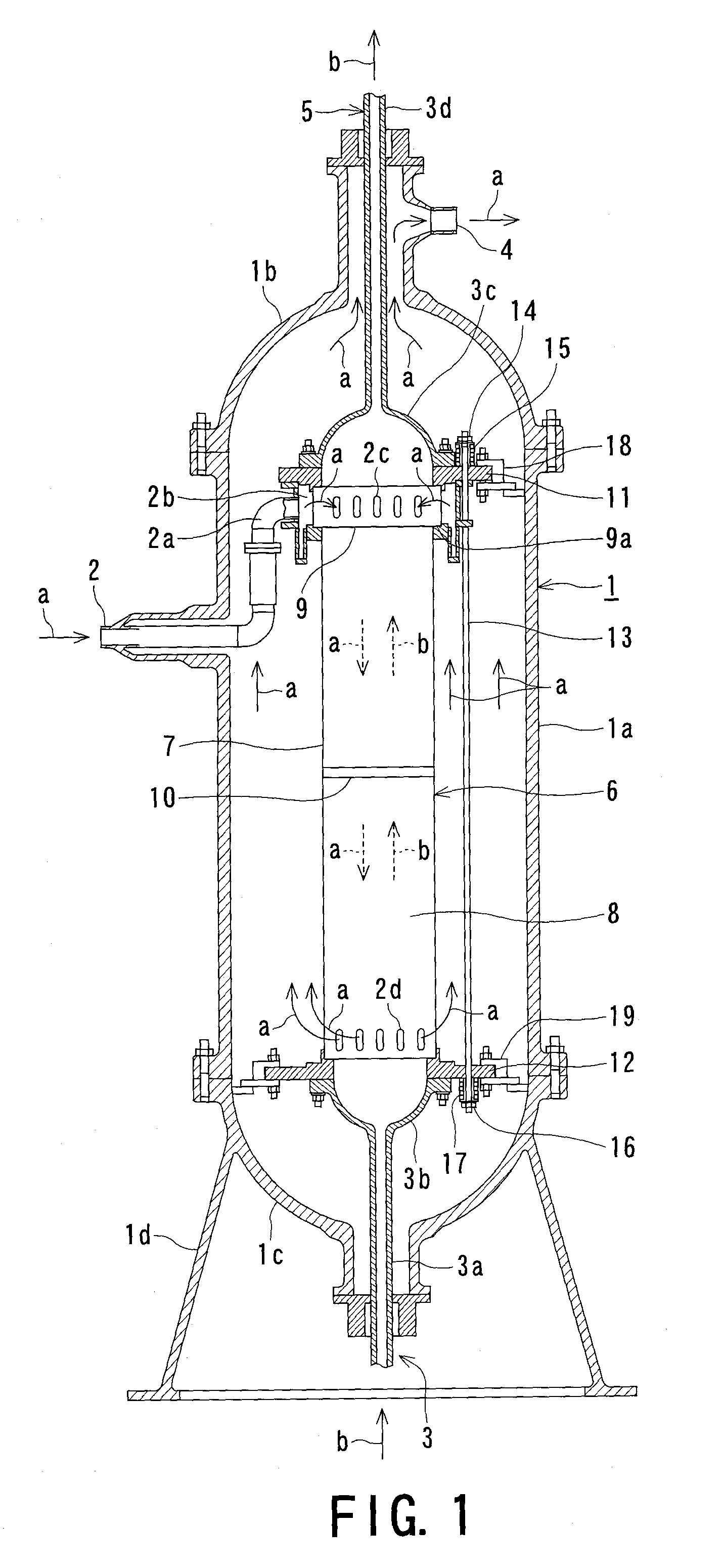
[0055]FIG. 1 is a general view of the structure of a ceramic heat exchanger according to a first embodiment of the present invention. The overall structure of the ceramic heat exchanger of a thermochemical IS process hydrogen production apparatus will be described hereunder with reference to FIG. 1.

[0056]As shown in FIG. 1, the ceramic heat exchanger of the present embodiment has a vertically oriented cylindrical pressure vessel 1. The pressure vessel 1 is a gas-tight enclosure including, for example, a barrel 1a and a hemispherical upper mirror portion 1b and lower mirror portion 1c disposed at the top and bottom of the barrel. The lower mirror 1c has a skirt-like support 1d. The support 1d fixes the pressure vessel 1 upright to a predetermined position on an installation floor.

[0057]A helium inlet nozzle 2 through which high-temperature helium gas a, or a first heat exchange fluid, is introduced is provided at an upper position in the wall of the barrel 1a of the press...

second embodiment

FIGS. 1, 9, and 10

[0088]This second embodiment represents a ceramic heat exchanger in which at least one of the ceramic blocks 7 and 8 has tapered portions 30 and 31 at the junction end at which the ceramic blocks 7 and 8 are joined. The tapered portions 30 and 31 have a diameter gradually increases toward the end. The peripheries of the tapered portions 30 and 31 are fitted with tapered rings 32 and 33, respectively. Flanges 36 and 37 having steps 34 and 35 to which the edges of the tapered rings 32 and 33 are seated are provided, and the flanges 36 and 37 are tightened to each other by means of a plurality of tie rods 38. The same parts as in the first embodiment are designated by the same reference numerals and the duplicated description will be omitted herein.

[0089]FIG. 9 is a specific representation of a tightening portion for tightening the ceramic blocks 7 and 8 as an example of the present embodiment.

[0090]In the present embodiment, as shown in FIG. 9, the ceramic blocks 7 a...

third embodiment

FIGS. 1 and 11 to 13

[0101]This third embodiment represents a ceramic heat exchanger having a plurality of ceramic blocks 7 and 8 stacked one on top of the other with a disassemblable seal 10 therebetween. End plates 11 and 12 are disposed outside the stack of the ceramic blocks 7 and 8 and bound with a plurality of tie rods 13 to join and integrate the ceramic blocks 7 and 8. Spacers 40 made of a material in the same series as the tie rods 13 or a material having a higher thermal expansion coefficient than the tie rods 13 are disposed between the end plate 12 and the end portions of the tie rods 13.

[0102]The linear expansion coefficient of ceramic, such as silicon carbide or silicon nitride, is about 4E-6 / ° C. and is lower than that of metals such as stainless steel or inconel. Consequently, the structure of the first or second embodiment in which a plurality of ceramic blocks 7 and 8 are joined and integrated with the seal 10 therebetween produces a thermal expansion difference at ...


PUM


Abstract

A ceramic heat exchanger includes a heat exchange section that heat-exchanges between two fluids A and B flowing opposite directions to each other. The heat exchange section includes ceramic blocks stacked one on top of another with a seal therebetween. The ceramic blocks have a plurality of parallel lines of flow channels, each line defined by the flow channels through which the same fluid flows, any two adjacent lines being defined by the flow channels through which the different fluids A and B flow respectively. Both ends in the stacking direction of the stack are bound to join and integrate the ceramic blocks with tightening means including end plates and a tie rod. A thermal expansion absorber is disposed on an external surface of the end plates for absorbing thermal expansion in the axial direction of the tie rod.

Description

TECHNICAL FIELD[0001]The present invention relates to ceramic heat exchangers used in the industries of nuclear energy, aerospace, chemicals and so forth, and particularly, relates to a heat exchanger suitable for a hydrogen production apparatus based on the thermochemical IS (iodine-sulfur) process that produces a large amount of hydrogen and oxygen from water material using nuclear heat.BACKGROUND ART[0002]A variety of heat exchangers are used in a wide range of industrial fields, such as nuclear industry, aerospace industry, chemical industry, and general industry. In particular, heat exchangers required to be resistant to high temperature and corrosion use a ceramic block as the heat exchange section. As an example of such heat exchange, a heat exchanger will now be described hereunder which is used in a thermochemical IS process hydrogen production apparatus for producing a large amount of hydrogen and oxygen from water material using nuclear heat of about 950° C.[0003]The IS p...

Claims


Application Information

Patent Timeline
IPC IPC(8): F28F3/08
CPCF28F7/02F28F21/04F28F2275/205F28F2230/00Y02E30/40F28F2265/26G21D1/02Y02E30/00Y02E30/30
Inventor INATOMI, TAKANARISAKAI, YASUHIROMARUYAMA, SHIGEKISUYAMA, SHOKOHINO, RYUTAROTERADA, ATSUHIKOONUKI, KAORUKUBO, SHINJIKASAHARA, SEIJI
Owner JAPAN ATOMIC ENERGY AGENCY INDEPENDANT ADMINISTRATIVE CORP
Why Eureka
Try Eureka