Stent with polymer coating containing amorphous rapamycin

a polymer coating and rapamycin technology, applied in the field of rapamycin amorphous rapamycin stents, can solve the problems of affecting the uniformity of the coating process of the substrate, affecting the uniformity of the coating,

Inactive Publication Date: 2009-03-05
MICELL TECH INC
View PDF98 Cites 58 Cited by
  • Summary
  • Abstract
  • Description
  • Claims
  • Application Information

AI Technical Summary

Benefits of technology

[0007]In yet another aspect, the invention provides a coated stent, wherein the rapamycin-polymer coating is sintered in dense carbon dioxide at a temperature of about 40 C to about 60 C, whereby bulk properties and adhesion of the coating to the stent are improved without altering the quality of the rapamycin, PBMA or PEVA. Preferably, the rapamycin-polymer coating covers substantially the entire surface of the stent framework and / or the rapamycin-polymer coating is substantially free of aggregated particles.

Problems solved by technology

Conventional solvent-based spray coating processes are generally hampered by inefficiencies related to collection of the coating constituents onto the substrate and the consistency of the final coating.
As the size of the substrate decreases, and as the mechanical complexity increases, it grows increasingly difficult to uniformly coat all surfaces of a substrate.

Method used


Image

  • Stent with polymer coating containing amorphous rapamycin
  • Stent with polymer coating containing amorphous rapamycin
  • Stent with polymer coating containing amorphous rapamycin

Examples


example 1

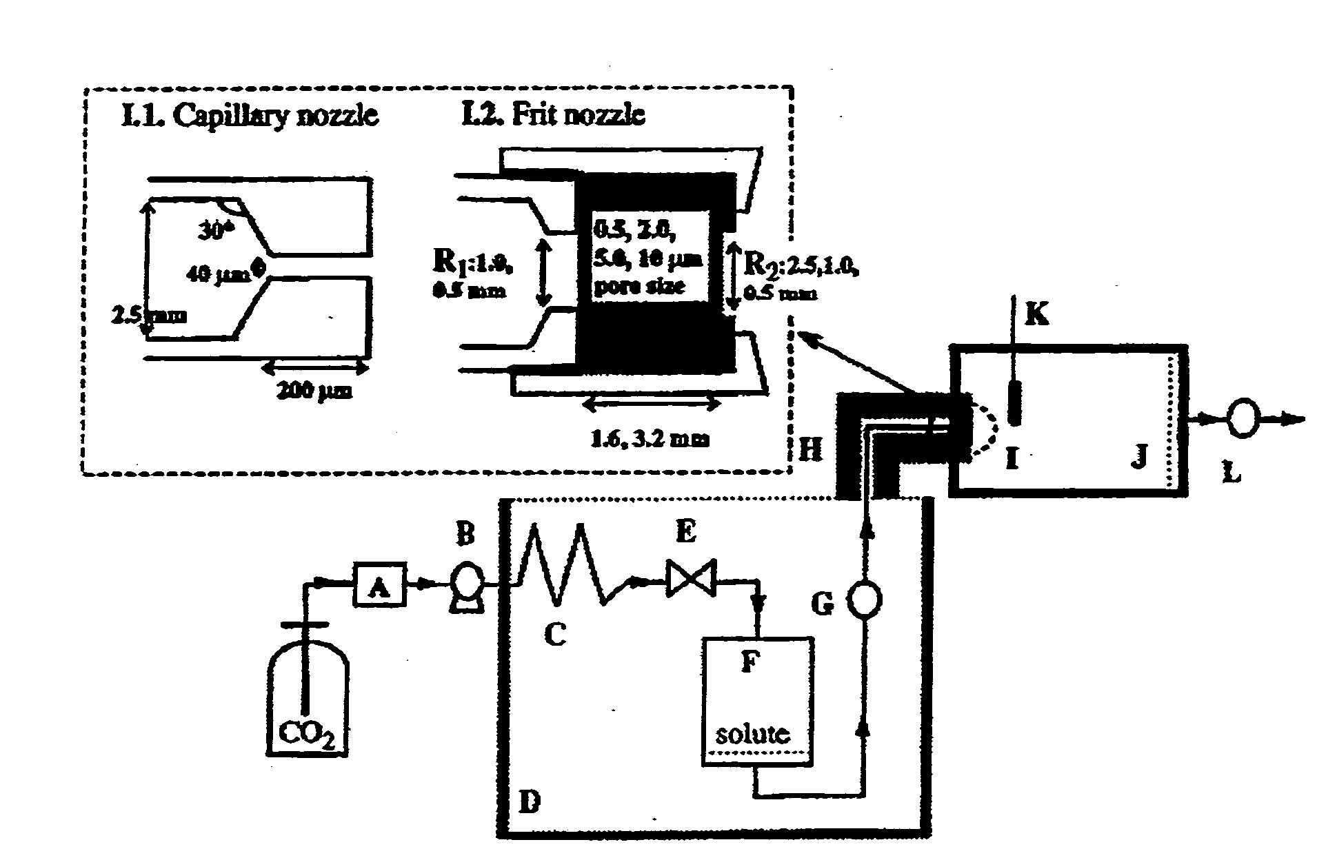
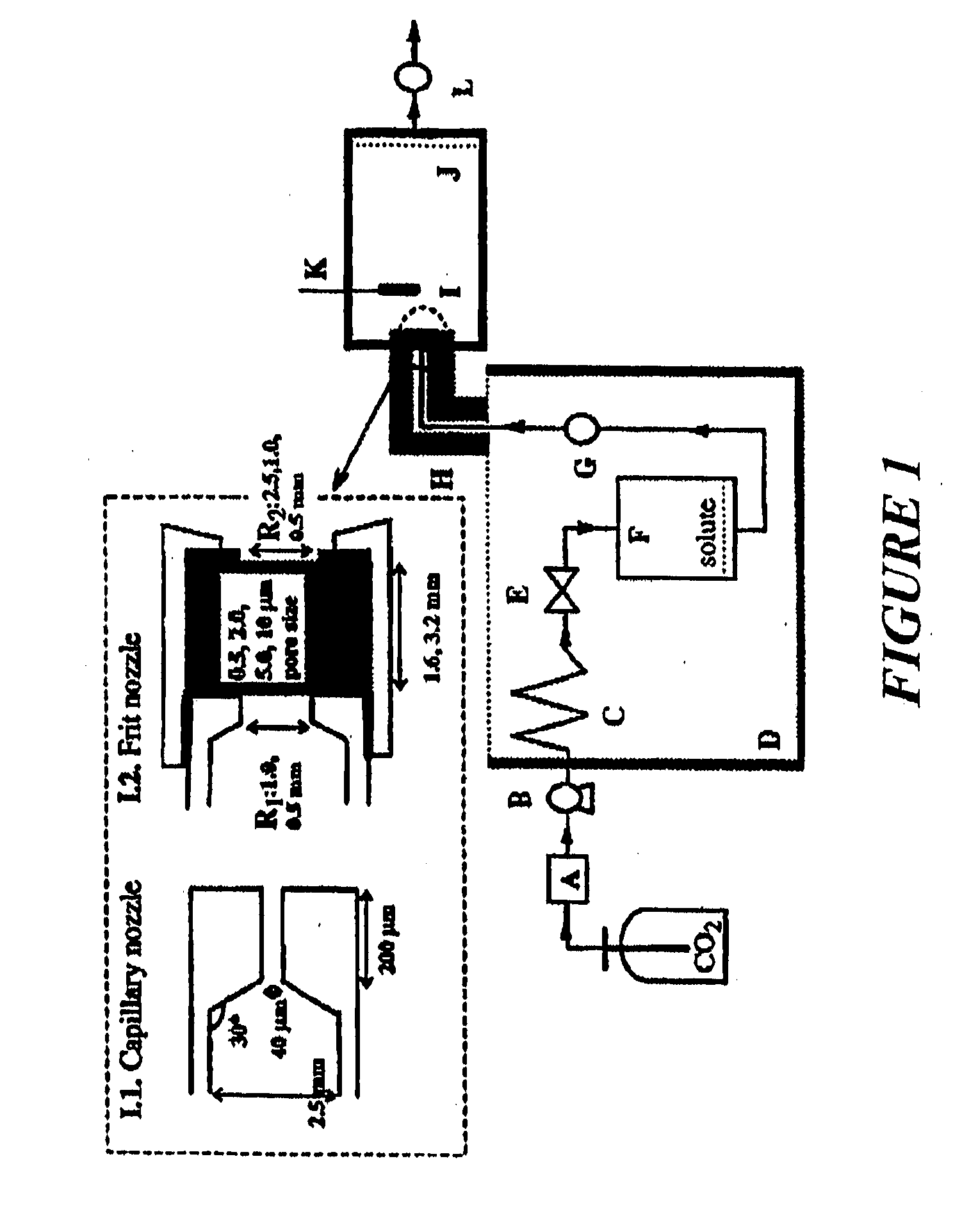
[0032]The RESS process equipment used in the present studies is depicted in FIG. 1. This is a common design for a RESS apparatus see C. Domingo et al, Journal of Supercritical Fluids 10, 39-55 (1997).

[0033]A solution containing rapamycin that is saturated in a solvent or supersaturated in a solvent is sprayed at a flow rate sufficient to achieve flow into a chamber of known volume pressurized above ambient pressure and containing a coronary stent. The system temperature is held constant or allowed to vary so that any number of points in the phase diagrams of the solution or mixture or any of its individual components can be mapped in pressure-temperature, volume-pressure or pressure-volume space constituting liquid, gas or supercritical CO2 conditions. CO2 in any single phase or combination of phases flows through the chamber at a mass flow rate of 5 gm / min to some multiple of this flow rate. After a period of time ranging from seconds to minutes or hours have elapsed, the solute an...

example 2

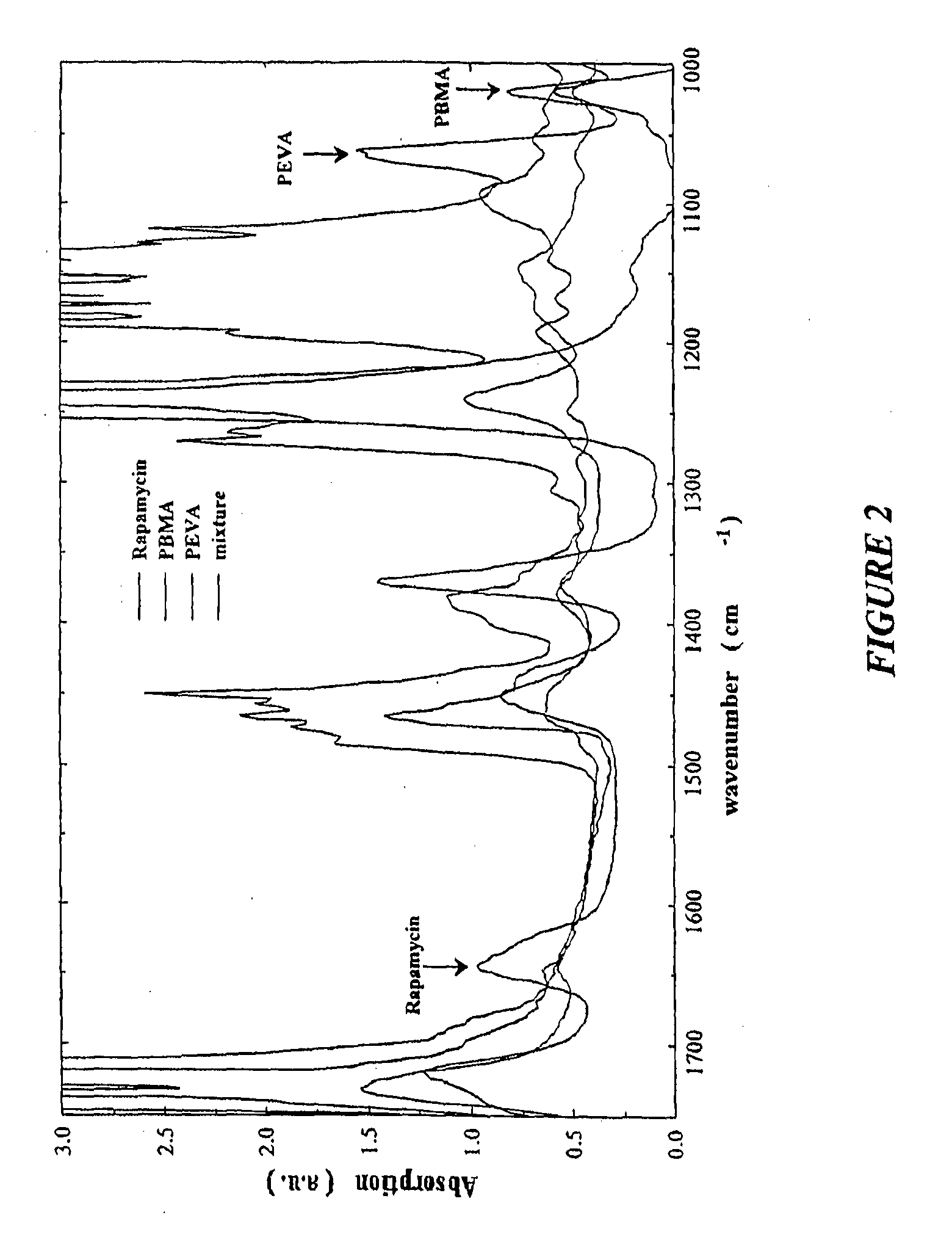
[0034]The ability to uniformly coat arterial stents with rapamycin with controlled composition and thickness using electrostatic capture in a rapid expansion of supercritical solution (RESS) experimental series has been demonstrated. This technique involves spraying an equal part mixture of the therapeutic compound such as rapamycin and polymers such as PBMA and PEVA using a spray coating and collection technique described herein. To determine coating composition, infrared spectroscopy was used to collect the spectrum of a silicon wafer chip coated simultaneously with an arterial stent (FIG. 2). Unique absorption bands were identified for each mixture component and band area was used as a metric to determine incorporation of each compound in the coating.

[0035]The individual bands used for compositional analysis were determined by spray coating Si wafer chips with each component separately. The coating thickness was determined gravimetrically and calculated from the density of the ma...


PUM

PropertyMeasurementUnit
diameteraaaaaaaaaa
thicknessaaaaaaaaaa
pressureaaaaaaaaaa

Abstract

A coated coronary stent, comprising: a stainless steel sent framework coated with a primer layer of Parylene C; and a rapamycin-polymer coating having substantially uniform thickness disposed on the stent framework, wherein the rapamycin-polymer coating comprises polybutyl methacrylate (PBMA), polyethylene-co-vinyl acetate (PEVA) and rapamycin, wherein substantially all of the rapamycin in the coating is in amorphous form and substantially uniformly dispersed within the rapamycin-polymer coating.

Description

BACKGROUND OF THE INVENTION[0001]It is often beneficial to provide coatings onto substrates, such that the surfaces of such substrates have desired properties or effects. It is useful to coat biomedical implants to provide for the localized delivery of pharmaceutical or biological agents to target specific locations within the body, for therapeutic or prophylactic benefit. One area of particular interest is drug eluting stents (DES) that has recently been reviewed by Ong and Sermuys in Nat. Clin. Pract. Cardiovasc. Med., (December 2005), Vol 2, No 12, 647. Typically such pharmaceutical or biological agents are co-deposited with a polymer. Such localized delivery of these agents avoids the problems of systemic administration, which may be accompanied by unwanted effects on other parts of the body, or because administration to the afflicted body part requires a high concentration of pharmaceutical or biological agent that may not be achievable by systemic administration. The coating m...

Claims


Application Information

Patent Timeline
Patent Type & Authority Applications(United States)
IPC IPC(8): A61F2/82
CPCA61F2250/0067A61F2/07A61F2240/002A61F2/86A61F2002/821A61L31/022A61L31/10A61L31/16A61L2300/216A61L2300/606A61L2420/08
Inventor TAYLOR, DOUGDEYOUNG, JAMESMCCAIN, JIM
Owner MICELL TECH INC
Why Eureka
Try Eureka